The Basics of Using the DS28E18
Abstract
This application note goes over the basics of using the DS28E18 1-Wire® to I2C/SPI Bridge with Command Sequencer and discusses the steps to get it up and running quickly. It then shows how to use the device with two different devices. The first device is an I2C humidity/temperature sensor and the second one is an SPI temperature sensor device. It concludes with detailed logs of each command.
Introduction
This application note discusses how to bring up the DS28E18 quickly. It then briefly goes over some simplified DS28E18-based systems. It also outlines the system operation flows and demonstrates some practical examples with an I2C and an SPI temperature sensor device. Refer to the DS18E18 data sheet for the detailed device operation and specifications. A Sensirion SHTC3 is used as the I2C device and a Maxim Integrated MAX31723 device as the SPI device.
DS28E18-Based Systems
The DS28E18 is used in two types of systems:
- A solitary DS28E18 connected to a 1-Wire controller (Figures 1 and 2). Figure 1 shows an I2C device and Figure 2 an SPI device.
- The second type of system can have multiple DS28E18 sharing the same 1-Wire bus connected to a 1-Wire bus controller (Figure 3).
All these figures are simplified to show the concept. Refer to the DS28E18 data sheet for implementation details.

Figure 1. Single DS28E18-based system with a connected I2C device.

Figure 2. Single DS28E18-based system with a connected SPI device.

Figure 3. Multiple DS28E18-based systems.
DS28E18 Operational Steps
The basic operation of the DS28E18 is divided into two steps:
- Initializing the DS28E18.
- Communicating with the connected device:
- I2C interface
- SPI interface
Let us look at the basic steps that make the DS28E18 such a versatile device before going into the details. The tried and true 1-Wire interface can be used to construct and write a sequence of up to 512 bytes to its sequencer memory. It consists of the commands and controls to operate the attached I2C or SPI device. The data written to the sequencer can be read back to verify if it is correctly written. The sequenced data can be then be sent to a connected I2C or SPI device. The DS28E18 sends the command, reads back the response and then stores it in its sequencer memory. The stored data then can be retrieved by reading the assigned sequencer locations. Figure 4 shows the simplified dataflow.

Figure 4. Write, read, and run sequence relationship of the DS28E18.
Initializing the DS28E18
The initialization steps of the device are outlined in Figure 5 (a system with a single DS28E18) and Figure 6 (a system with multiple DS28E18s on the 1-Wire bus).

Figure 5. Single DS28E18-based system.
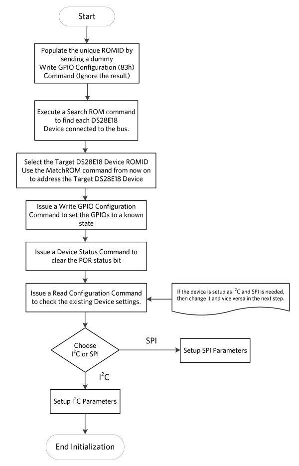
Figure 6. Multiple DS28E18-based systems.
Initializing the DS28E18
Step 1. Populate the unique ROM ID of all devices on the 1-Wire line by sending a dummy Write GPIO Configuration (83h) Command (ignore the result).
1-Wire command sent: RP CC 66 05 83 0B 03 A5 0F [75] [02] AA
Explanation:
RP: Reset Pulse
CC: Skip ROM
66: Command Start
05: Number of Bytes
83: Write GPIO Configuration
0B: Sets Access to the GPIO control Register
03: Only value allowed
A5: GPIO_CTRL_HI Value
0F: GPIO_CTRL_LO Value
75: CRC16_1
02: CRC16_2
AA: Release Byte
Result: [FF] [01] [77] [BE] [49] – Ignore the failure
Step 2. Execute a Search ROM Command to find each DS28E18 device connected to the bus.
In this example, a single device is connected to the 1-Wire bus and the ROM ID is: 56708E0000000043
Step 3. Issue a Write GPIO Configuration Command to set the GPIOs to a known state.
1-Wire command sent: RP 55 56 70 8E 00 00 00 00 43 66 05 83 0B 03 A5 0F [75] [02] AA
Explanation:
RP: Reset Pulse
55: Match ROM
Next 8 Bytes: The Target Device ROMID
66: Command Start
05: Number of Bytes
83: Write GPIO Configuration
0B: Sets Access to the GPIO control Register
03: Only value allowed
A5: GPIO_CTRL_HI Value
0F: GPIO_CTRL_LO Value
75: CRC16
02: CRC16
AA: Release Byte
Result: [FF] [01] [AA] [7E] [10]
Explanation:
FF: Dummy Byte
01: Length Byte
AA: Result Byte - Success
7E: CRC16
10: CRC16
Step 4. Issue a Device Status Command to clear the POR status bit.
1-Wire command sent: RP 55 56 70 8E 00 00 00 00 43 66 01 7A [9F] [93] AA
Explanation:
RP: Reset Pulse
55: Match ROM
Next 8 Bytes: The Target Device ROMID
66: Command Start
01: Number of Bytes
7A: Device Status Command
9F: CRC16
93: CRC16
AA: Release Byte
Result: [FF] [05] [AA] [02] [00] [00] [00] [E6] [0A]
Explanation:
FF: Dummy Byte
05: Length Byte
AA: Result Byte - Success
02: POR Has occurred
00: Device Version
00: MANID[0]
00: MANID[1]
E6: CRC16
0A: CRC16
Step 5. Issue a Read Configuration Command to check the existing device settings.
1-Wire command sent: RP 55 56 70 8E 00 00 00 00 43 66 01 6A [9E] [5F] AA
Explanation:
RP: Reset Pulse
55: Match ROM
Next 8 Bytes: The Target Device ROMID
66: Command Start
01: Number of Bytes
6A: Read Configuration Command
9E: CRC16
5F CRC16
AA: Release Byte
Result: [FF] [02] [AA] [01] [E1] [5F]
Explanation:
FF: Dummy Byte
02: Length Byte
AA: Result Byte – Success
01: Configuration Register Value
- PROT: I2C
- INACK: Do not ignore
- SPD: 400 kHz
7E: CRC16
10: CRC16
Step 6. This DS28E18 is already set to I2C mode. But, just as an exercise, let us set the I2C speed to 1MHz. Let us also do a Read Configuration to verify, and then show how to set the device to the SPI mode.
There is one device on the bus in this example. So, Skip ROM is used in some of the following commands.
Write Configuration Command to set the I2C speed to 1MHz
1-Wire command sent: RP CC 66 02 55 02 [FE] [26] AA
Explanation:
RP: Reset Pulse
CC: Skip ROM (With one device on the bus, the Skip Rom Command can be used.)
66: Command Start
02: Number of Bytes
55: Write Configuration Command
02: Configuration Register
- PROT: I2C
- INACK: Do not ignore
- SPD: 1 MHz
FE: CRC16
26: CRC16
AA: Release Byte
Result: [FF] [01] [AA] [7E] [10]
Explanation:
FF: Dummy Byte
01: Length Byte
AA: Result Byte - Success
7E: CRC16
10: CRC16
Read Configuration Command to verify that the speed is now set to 1MHz
1-Wire command sent: RP 55 56 70 8E 00 00 00 00 43 66 01 6A [9E] [5F] AA
Explanation:
RP: Reset Pulse
55: Match ROM
Next 8 Bytes: The Target Device ROMID
66: Command Start
01: Number of Bytes
6A: Read Configuration Command
9E: CRC16
5F CRC16
AA: Release Byte
Result: [FF] [02] [AA] [02] [A1] [5E]
Explanation:
FF: Dummy Byte
02: Length Byte
AA: Result Byte – Success
02: Configuration Register Value
- PROT: I2C
- INACK: Do not ignore
- SPD: 1 MHz
A1: CRC16
5E CRC16
Write Configuration Command to set the DS28E18 to the SPI Mode
1-Wire command sent: RP CC 66 02 55 38 [7E] [35] AA
Explanation:
RP: Reset Pulse
CC: Skip ROM (With one device on the bus, the Skip Rom Command can be used.)
66: Command Start
02: Number of Bytes
55: Write Configuration Command
38: Configuration Register
- PROT: SPI
- SPI MODE: 3
- SPD: 100 kHz
7E: CRC16
35: CRC16
AA: Release Byte
Result: [FF] [01] [AA] [7E] [10]
Explanation:
FF: Dummy Byte
01: Length Byte
AA: Result Byte - Success
7E: CRC16
10: CRC16
DS28E18 initialization is now complete.
Communicating with a Connected Device
Let us now look at two different examples of communicating with a connected device. The first device is the Sensirion SHTC3 temperature and humidity sensor, and the second one is the MAX31723 temperature sensor. Figure 7 shows the general communication flow with a connected sensor device.

Figure 7. DS28E18 basic communication flow with connected devices.
Sensirion SHTC3 I2C Temperature and Humidity Sensor
Here are some highlights of the SHTC3 Device:
- I2C communication: The I2C Address in hexadecimal is 0xE0 for Write and 0xE1 for Read.
- Use the following command sequence to measure the sensor data:
- Wakeup2 – 0x3517
- Maximum wakeup time is 240us – Let us use 1ms.
- Measure2 –¬ 0x5C24 (Read RH First. Normal Mode).
- Maximum measurement wait time in normal mode is 12.1 ms – Let us use 16ms.
- Wait for the measurement wait time after the Measure command is issued. Then capture and read back 6 bytes of data.
- The first two bytes are humidity MSB first.
- The third byte is the humidity CRC.
- The 4th and 5th bytes are the temperature data MSB first.
- The 6th byte is the temperature CRC.
The following formulas are used to calculate the humidity and temperature values from the measured raw data:

The following are the complete flow and explanation of the measurements. The calculated values are shown at the end of the flow.
Communicating with the Sensirion SHTC3 Device. Example Command Flow
Initialize the DS28E18 to the I2C mode, 1MHz, and do not Ignore NACK.
Step 1. Build the command sequence and write the sequencer.
- Send the Wakeup Command 0x3517
- Sent the Measure Command 0x5C24
- Read Back 6 bytes of Data
1-Wire command sent: RP CC 66 22 11 00 00 02 E3 03 E0 35 17 03 DD 00 02 E3 03 E0 5C 24
03 DD 04 02 E3 01 E1 D4 06 FF FF FF FF FF FF 03 [B9] [F8] AA
Explanation:
RP: Reset Pulse
CC: Skip ROM (With one device on the bus, the Skip Rom command can be used.)
66: Command Start
22: Number of Bytes
11: Write Sequencer Command
00: ADDR_LO
00: ADDR_HI
02: I2C Start – This is the start of the sequencer data
E3: I2C Write Data – DS28E18 Sequencer Command
03: Write Length – Number of Bytes – 3 bytes sent to the SHTC3
E0: SHTC3 I2C Write Address
35: SHTC3 Wakeup Command byte 1
17: SHTC3 Wakeup Command byte 2
03: I2C Stop
DD: DS28E18 Delay Command – SHTC2 Wakeup Delay
00: 1ms delay
02: I2C start
E3: I2C Write Data – DS28E18 Sequencer Command
03: Write Length – Number of Bytes – 3 bytes that will be sent to the SHTC3
E0: SHTC3 I2C Write Address
5C: SHTC3 Measure Command byte 1
24: SHTC3 Measure Command byte 1
03: I2C Stop
DD: DS28E18 Delay Command – SHTC2 Measurement Delay
04: 16ms delay
02: I2C Start
E3: I2C Write Data – DS28E18 Sequencer Command
01: Write Length – Number of Bytes – 1 byte will be sent to the SHTC3
E1: SHTC3 I2C Read Address
D4: DS28E18 I2C Read Data Command
06: Number of Bytes to Read
FF: Place holder for Byte 1 – DS28E18 will read the data back and put it in here
FF: Place holder for Byte 2
FF: Place holder for Byte 3
FF: Place holder for Byte 4
FF: Place holder for Byte 5
FF: Place holder for Byte 6
03: I2C Stop – Sequencer ends here
B9: CRC16
F9: CRC16
AA: Release Byte
Result: [FF] [01] [AA] [7E] [10]
Explanation:
FF: Dummy Byte
01: Length Byte
AA: Result Byte - Success
7E: CRC16
10: CRC16
Step 2. Issue a Read Sequencer Command to read back the data.
1-Wire command sent: RP CC 66 03 22 00 3E [D6] [69] AA
Explanation:
RP: Reset Pulse
CC: Skip ROM (With one device on the bus, the Skip Rom Command can be used.)
66: Command Start
03: Number of Bytes
22: Read Sequencer Command
00: ADDR_LO
3E: SLEN:ADDR_HI
D6: CRC16
69: CRC16
AA: Release Byte
Result: [FF] [20] [AA] [02] [E3] [03] [E0] [35] [17] [03] [DD] [00] [02] [E3] [03] [E0] [5C] [24] [03] [DD] [04] [02] [E3] [01] [E1] [D4] [06] [FF] [FF] [FF] [FF] [FF] [FF] [03] [14] [F1]
Data read back:
[02][E3][03][E0][35][17][03][DD][00][02][E3][03][E0][5C][24][03][DD][04][02][E3][01][E1][D4][06][FF][FF][FF][FF][FF][FF][03]
Step 3. Issue a Run Sequencer Command to execute the sequence. This command errors out if the sequencer is not properly constructed.
1-Wire command sent: RP CC 66 04 33 00 3E 00 [18] [DD] AA
Explanation:
RP: Reset Pulse
CC: Skip ROM (With one device on the bus, the Skip Rom Command can be used.)
66: Command Start
04: Number of Bytes
33: Read Sequencer Command
00: ADDR_LO
3E: SLEN_LO:ADDR_HI
00: SLEN_HI
18: CRC16
DD: CRC16
AA: Release Byte
Result: [FF] [01] [AA] [7E] [10]
Explanation:
FF: Dummy Byte
01: Length Byte
AA: Result Byte - Success
7E: CRC16
10: CRC16
Now let us look at what is there in the sequencer and what happened when the Run Sequencer Command was issued.
| Sequencer Address | Data Byte | Command Description |
|---|---|---|
| 0000 | 02 | I2C Start Command |
| 0001 | E3 | I2C Write Data Command - DS28E18 |
| 0002 | 03 | I2C Write Length |
| 0003 | E0 | I2C Write Data - SHTC3 Write Address |
| 0004 | 35 | I2C Write Data - SHTC3 Wakeup Command Byte 1 |
| 0005 | 17 | I2C Write Data - SHTC3 Wakeup Command Byte 2 |
| 0006 | 03 | I2C Stop Command |
| 0007 | DD | Delay Command - DS28E18 |
| 0008 | 00 | Delay Parameter - 1ms |
| 0009 | 02 | I2C Start Command |
| 000A | E3 | I2C Write Data Command - DS28E18 |
| 000B | 03 | I2C Write Length |
| 000C | E0 | I2C Write Data - SHTC3 Write Address |
| 000D | 5C | I2C Write Data - SHTC3 Measure Command Byte 1 |
| 000E | 24 | I2C Write Data - SHTC3 Measure Command Byte 2 |
| 000F | 03 | I2C Stop Command |
| 0010 | DD | Delay Command - DS28E18 |
| 0011 | 04 | Delay Parameter - 16ms |
| 0012 | 02 | I2C Start Command |
| 0013 | E3 | I2C Write Data Command - DS28E18 |
| 0014 | 01 | I2C Write Length |
| 0015 | E1 | I2C Write Data - SHTC3 Read Address |
| 0016 | D4 | I2C Read Data Command - DS28E18 |
| 0017 | 06 | I2C Read Length |
| 0018 | FF | I2C Read Data Placeholder - Byte 1 |
| 0019 | FF | I2C Read Data Placeholder - Byte 2 |
| 001A | FF | I2C Read Data Placeholder - Byte 3 |
| 001B | FF | I2C Read Data Placeholder - Byte 4 |
| 001C | FF | I2C Read Data Placeholder - Byte 5 |
| 001D | FF | I2C Read Data Placeholder - Byte 6 |
| 001E | 03 | I2C Stop Command |
Thus, this complete sequence of data was executed when the Run Sequencer command was issued. The SHTC3 was instructed to wake up, take a measurement, and send back the result to the DS28E18. The DS28E18 received the data and stored it in the place holder bytes shown in Table 1.
Step 4. Issue a Read Sequencer Command to read back the stored humidity and temperature data from the DS28E18 sequencer address 0x0018 to 0x001D.
1-Wire command sent: RP CC 66 03 22 18 0C [5D] [BC] AA
Explanation:
RP: Reset Pulse
CC: Skip ROM (With one device on the bus, the Skip Rom Command can be used.)
66: Command Start
03: Number of Bytes
22: Read Sequencer Command
18: ADDR_LO
0C: SLEN:ADDR_HI
5D: CRC16
BC: CRC16
AA: Release Byte
Result: [FF] [07] [AA] [73] [CB] [3A] [65] [38] [DF] [54] [5F]
Data Read back 6 bytes from the sequencer: [73][CB][3A][65][38][DF]
Step 5. Calculate the humidity and temperature.
Sensor RH data = 0x73CB = 29643d
Sensor T data = 0x6538 = 25912d
Relative Humidity (%RH) = 100 x (29643/65536) = 45.23%
Temperature = −45 + 175 x (25912/65536) = 24.19°C
Maxim Integrated MAX31723 SPI Temperature and Humidity Sensor
The following are some highlights of the MAX31723:
- The SPI mode of the serial communication is selected by connecting the SERMODE to VDD.
- The devices powers-up in a power-conserving shutdown mode. The devices can be placed in a continuous or one-shot conversion mode after power-up.
- The configuration/status register is accessed in the devices with the 00h address for reads and 80h address for writes.
- The MSB (A7) of the address byte determines if a read or write takes place. One or more read cycles occur if A7 is 0. One or more write cycles occur if A7 is 1.
- The configuration register power-up state is 0x01.
- The configuration register must be set to 0x00 to enable the continuous temperature conversion mode.
- The temperature MSB register provides the decimal part of the temperature read. 0x17 => 23°C and 0x18 => 24°C
Communicating with the MAX31723 Device. Example Command Flow
Initialize the DS28E18 to the SPI mode 3 and 100kHz speed. This example covers the following items:
- Configure the MAX31723 for temperature measurement. Refer to the MAX31723 data sheet for command details.
- Issue the measure command to the MAX31723 and measure the temperature data using the SPI Write/Read Byte.
- Issue the measure command to the MAX31723 and measure the temperature data using the SPI Write/Read Bit.
Configure the MAX31723 for temperature measurement
Step 1. Issue the Write Sequencer Command to write the DS28E18 sequencer memory for the MAX31723 configuration.
Write MAX31723 Config Byte to 00h:
80 //ss_low
DD //Delay
03 //8ms
01 //ss_high
C0 //spi write/read byte
02 //write len
00 //read len
80 //write data (MAX31723 register address, write)
00 //write data (MAX31723 Configuration register)
80 //ss_low
1-Wire command sent: RP CC 66 0D 11 00 00 80 DD 03 01 C0 02 00 80 00 80 [D3] [E9] AA
Result: [FF] [01] [AA] [7E] [10] – Write Sequencer Command Passed.
Step 2. Issue the Read Sequencer Command to verify the sequencer data.
1-Wire command sent: RP CC 66 03 22 00 14 [57] [B6] AA
Result: [FF] [0B] [AA] [80] [DD] [03] [01] [C0] [02] [00] [80] [00] [80] [C3] [1E]
Byte 0: 80
Byte 1: DD
Byte 2: 03
Byte 3: 01
Byte 4: C0
Byte 5: 02
Byte 6: 00
Byte 7: 80
Byte 8: 00
Byte 9: 80
Read Sequencer Command Passed.
Step 3. Issue the Run Sequencer Command to configure the MAX31723.
1-Wire command sent: RP CC 66 04 33 00 14 00 [07] [BD] AA
Result: [FF] [01] [AA] [7E] [10] – Run Sequencer Command Passed.
The MAX31723 is now ready for temperature measurement.
Measure the temperature data using the SPI Write/Read Byte
Step 1: Issue the Write Sequencer Command to write the DS28E18 sequencer memory to setup the MAX31723 for temperature measurement (SPI Write/Read Byte).
Setup Read Back Temp Data from the MAX31723
01 //ss_high
C0 //spi write/read byte
01 //write len
04 //read len
00 //write data (MAX31723 register address, read)
ff //read data place holder (dummy read)
ff //read data place holder (MAX31723 status register)
ff //read data place holder (MAX31723 temperature LSB register)
ff //read data place holder (MAX31723 temperature MSB register)
80 //ss_low
1-Wire command sent: RP CC 66 0D 11 00 00 01 C0 01 04 00 FF FF FF FF 80 [F8] [A5] AA
Result: [FF] [01] [AA] [7E] [10] - Write Sequencer Command Passed.
Step 2. Issue the Read Sequencer Command to verify the sequencer data.
1-Wire command sent: RP CC 66 03 22 00 14 [57] [B6] AA
Result: [FF] [0B] [AA] [01] [C0] [01] [04] [00] [FF] [FF] [FF] [FF] [80] [E8] [52]
Byte 0: 01
Byte 1: C0
Byte 2: 01
Byte 3: 04
Byte 4: 00
Byte 5: FF
Byte 6: FF
Byte 7: FF
Byte 8: FF
Byte 9: 80
Read Sequencer Command Passed.
Step 3. Issue the Run Sequencer Command to measure the temperature.
1-Wire command sent: RP CC 66 04 33 00 14 00 [07] [BD] AA
Result:[FF] [01] [AA] [7E] [10] - Run Sequencer Command Passed.
Step 4. Issue the Read Sequencer Command to read the temperature data from the DS28E18 sequencer.
1-Wire command sent: RP CC 66 03 22 05 08 [55] [2F] AA
Result: [FF] [05] [AA] [FF] [00] [80] [17] [F6] [68]
Byte 0: FF
Byte 1: 00
Byte 2: 80
Byte 3: 17
Read Sequencer Command Passed.
Measured Temp Data is: 1780h
Measured Temperature: 23.5°C (25°C is 1910h)3
Measure the temperature data using the SPI Write/Read Bit
Step 1: Issue the Write Sequencer Command to write the DS28E18 sequencer memory to setup the MAX31723 for temperature measurement (SPI Write/Read Bit).
MAX31723 SPI Write/Read Bit Sequence
01 //ss_high
B0 //spi write/read bit
08 //write len
18 //read len
00 //write data (MAX31723 register address, read)
ff //read data place holder (MAX31723 status register)
ff //read data place holder (MAX31723 temperature LSB register)
ff //read data place holder (MAX31723 temperature MSB register)
80 //ss_low
1-Wire command sent: RP CC 66 0C 11 00 00 01 B0 08 18 00 [FF] [FF] [FF] 80 [78] [E1] AA
Result: [FF] [01] [AA] [7E] [10] - Write Sequencer Command Passed.
Step 2. Issue the Read Sequencer Command to verify the sequencer data.
1-Wire command sent: RP CC 66 03 22 00 12 [D7] [B4] AA
Result: [FF] [0A] [AA] [01] [B0] [08] [18] [00] [FF] [FF] [FF] [80] [34] [0D]
Byte 0: 01
Byte 1: B0
Byte 2: 08
Byte 3: 18
Byte 4: 00
Byte 5: FF
Byte 6: FF
Byte 7: FF
Byte 8: 80
Read Sequencer Command Passed.
Step 3. Issue the Run Sequencer Command to measure the temperature.
1-Wire command sent: RP CC 66 04 33 00 12 00 [04] [1D] AA
Result:[FF] [01] [AA] [7E] [10] - Run Sequencer Command Passed.
Step 4. Issue the Read Sequencer Command to read the temperature data from the DS28E18 sequencer.
1-Wire command sent: RP CC 66 03 22 05 06 [D4] [EB] AA
Result: [FF] [04] [AA] [00] [80] [17] [0E] [29]
Byte 0: 00
Byte 1: 80
Byte 2: 17
Read Sequencer Command Passed.
Measured Temp Data is: 1780h
Measured Temperature: 23.5°C (25°C is 1910h)3
Summary
This application note covers the basic operations of the DS28E18, and how to get it up and running quickly to measure various sensor data. The same principles can be easily applied to communicate with any device with an I2C or SPI interface.