Multichannel RF-to-Bits Development Platform Enables Rapid Prototyping for Phased Arrays
Introduction
The industry trend for future antenna designs is phased array implementations. This technology trend, combined with time-to-market pressures forcing reduced development times, results in several challenges for RF designers in phased array systems. Some of the challenges related to the RF electronics include:
- Validation of the RF electronics in a multichannel environment
- Validation of synchronization and calibration across channels
- Software development in parallel with production hardware development
To address this industry challenge, there is a new multichannel RF-to-bits development platform based on a software-configurable high speed converter. The development platform integrates data converters, RF distribution, power regulation, and clocking to provide a 16-channel, direct S-band sampling solution.
Integrated RF Sampling High Speed Converters
The latest releases of high speed converters integrate ADCs, DACs, and digital signal processing blocks on monolithic silicon. The MxFE™ quad-channel, 16-bit, 12 GSPS, RF DAC and quad-channel, 12-bit, 4 GSPS, RF ADC shown in Figure 1 is one example and includes four ADCs, four DACs, and digital up/downconverters, as well as numerically controlled oscillators (NCOs) and finite-impulse response (FIR) digital filters. The DACs are rated to a sample rate of 12 GSPS and the ADCs are rated to 4 GSPS. Analog bandwidths provide direct sampling and waveform generation through S-band and into low C-band.

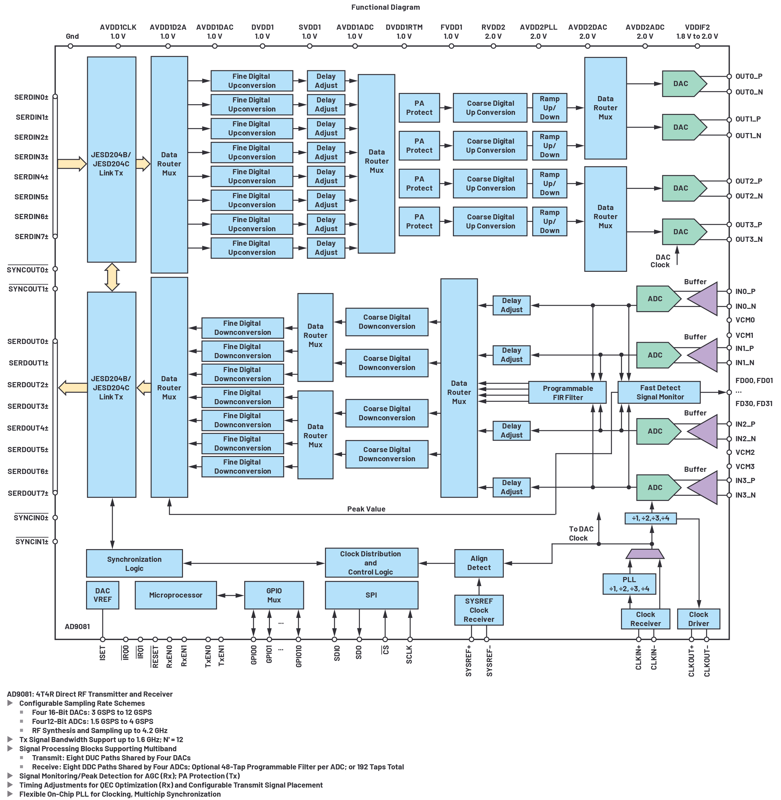
Figure 1. AD9081 functional description.
The converters process more of the RF spectrum band and embed DSP functions on-chip to enable the user to configure programmable filters and digital upconversion and downconversion blocks to meet specific radio signal bandwidth requirements. The embedded processing in dedicated silicon results in a significant power reduction compared to architectures that perform these functions in an FPGA. Freeing up valuable FPGA resources allows designers to use a more cost-effective FPGA, or allocate the FPGA resources to higher level system application processing.
16-Channel, Direct RF Sampling Development Platform (Quad MxFE)
The 16-channel, direct RF sampling development platform is shown in Figure 2 with the block diagram in Figure 3. To explain the naming convention: we name the integrated converters as mixed-signal front ends (MxFEs), and the 16-channel board contains four MxFEs and has been named the quad MxFE. With four MxFEs containing four DACs and ADCs each, there are 16 channels of transmit and 16 channels of receive.

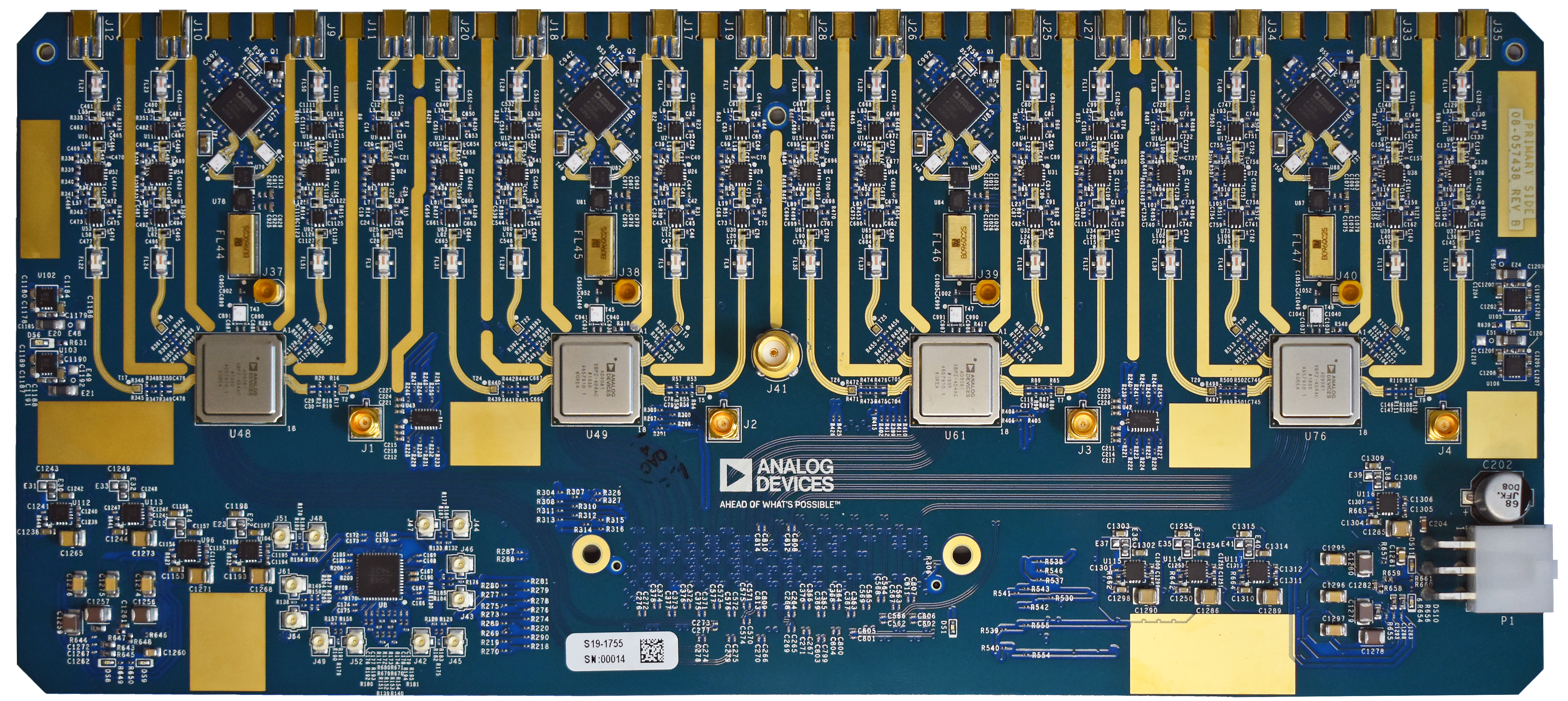
Figure 2. The 16-channel, direct RF sampling development platform (quad MxFE).

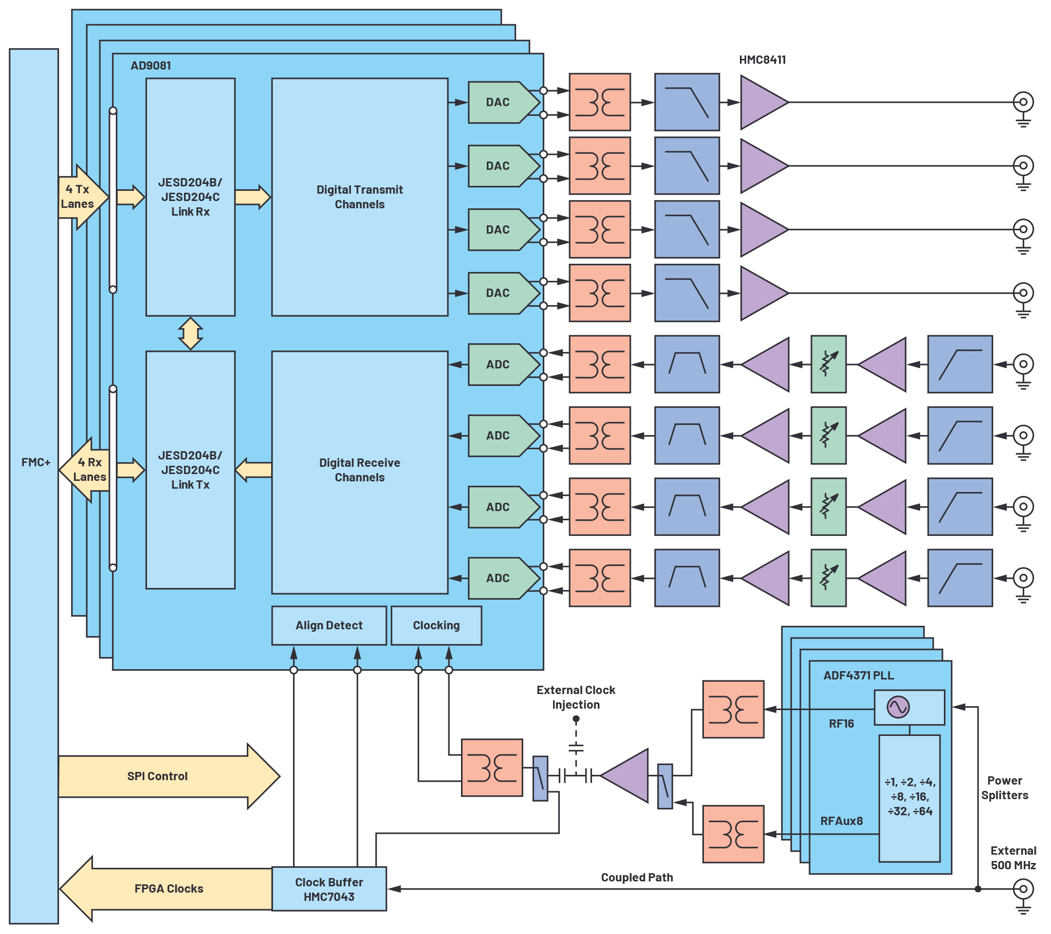
Figure 3. Quad MxFE block diagram.
The RF sections contain baluns, amplifiers, and filters to simplify the RF interface. On a transceiver channel, a low-pass filter is included to suppress the DAC image along with a gain block typical at a DAC output. On a receiver channel, two gain stages and gain control are included along with bandpass filters for second-order Nyquist sampling. Filters are in Mini-Circuits’ 1206 filter footprints to allow users to swap filters for alternate applications.
The channel spacing is implemented at 600 mils per T/R pair, which supports an X-band, half-wavelength, single-pole element lattice spacing. At this footprint, the design demonstrates compatibility for every element digital beamforming system up to X-band frequencies. With the quad MxFE generating S-band directly, a single additional RF mix can be added to enable X-band frequency operation.
Clocking circuitry is included, and all clocks are derived from a common reference frequency. PLLs are provided per converter that phase lock to the reference frequency and provide the AD9081 clock inputs. A test point injection option is included for evaluation with an alternate converter clock source. Digital clocks are also derived from the common reference frequency. A clock chip is included that provides SYSREF to the AD9081 for synchronization, clocks needed for the FPGA, and an option to provide the AD9081 a reference frequency allowing use of the PLL internal to the AD9081.
Power distribution and regulation is included as shown in Figure 4. All required voltages are derived from a single 12 V input. The power distribution design includes a combination of switching regulators, followed by low noise linear regulators for sensitive analog voltages.

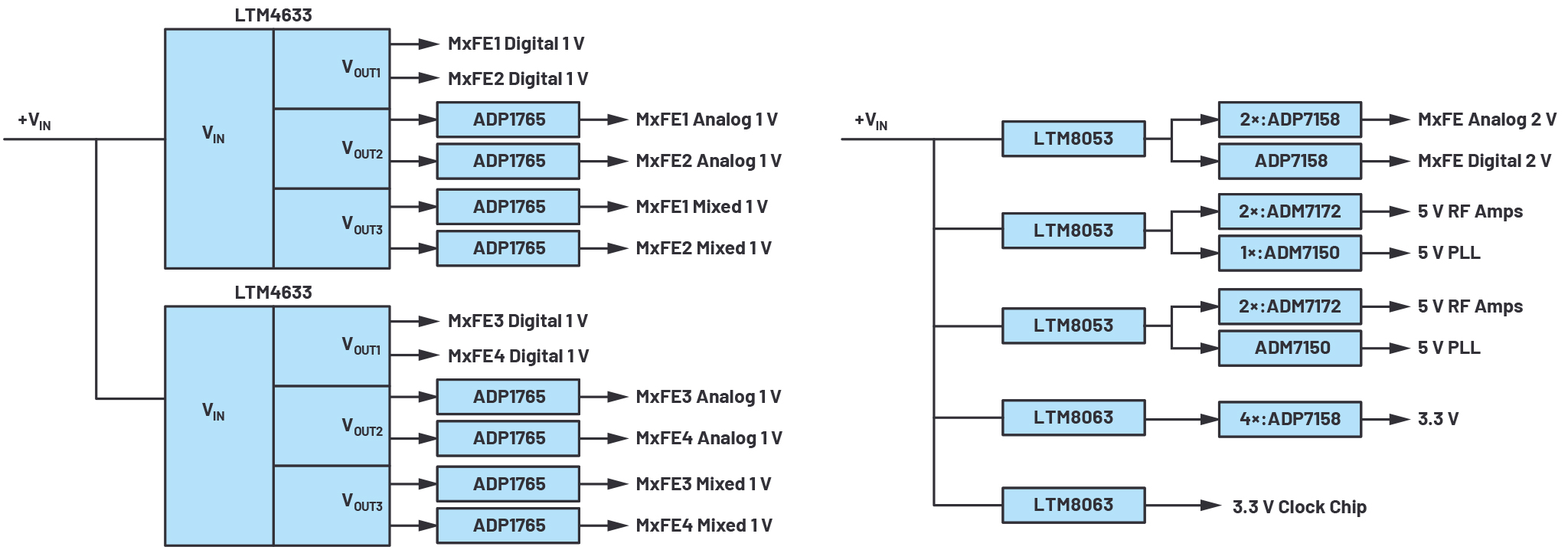
Figure 4. Quad MxFE power distribution.
Software Control
Software, firmware, and FPGA code have been developed to enable control of the platform through higher level processing languages. MATLAB® scripts and GUIs have been written to allow system engineers developing models to interface directly to the hardware in a MATLAB environment. The MATLAB interface enables evaluation with custom waveforms tested in simulation to be evaluated directly in the hardware. The receive data capture interface enables user-specific processing of the receive data.
Software and firmware are all open source, similar to other Analog Devices modules based around our latest transceivers or converters.
Conclusion
The quad MxFE RF-to-bits development platform enables a versatile prototyping environment. The capabilities include:
- Development platform to show multichannel synchronization across converter ICs and across boards.
- Validation of multichannel performance in an evaluation board environment prior to a customer instead committing to a production design with the sole purpose to test multiple channels simultaneously.
- A level of integration and functionality enabling software development in parallel with hardware productization.
- A complete reference design of all circuitry surrounding the high speed converters including RF I/O, clocking and synchronization circuits, power distribution, and high speed digital I/O routing.
The combination of these capabilities can remove a prototyping step in multichannel RF system product development, allowing RF engineers to leverage an implementation and focus their efforts on a system solution. The RF-to bits development platform was initially intended to enable phased array developments. However, the versatility it offers has gained applicability to any multichannel RF system such as radar, EW, 5G, and instrumentation applications. The result is a single-hardware, multiple application platform providing a truly software-defined multichannel environment.