Overview
Design Resources
Design & Integration File
- Schematic
- Bill of Materials
- PCB Layout
- Fab Package
Evaluation Hardware
Part Numbers with "Z" indicate RoHS Compliance. Boards checked are needed to evaluate this circuit.
- MAXREFDES178# ($169.00) EV Kit
Device Drivers
Software such as C code and/or FPGA code, used to communicate with component's digital interface.
Description
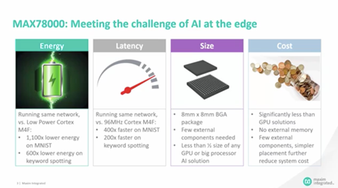
The MAX78000 is an Arm Cortex M4F microcontroller with a Convolutional Neural Network (CNN) accelerator unit. The unique energy-efficient architecture of the MAX78000 enables battery-powered AI for at the edge applications such as face identification and keyword spotting. The MAXREFDES178 is a cube camera reference design based on the MAX78000 and MAX32666 microcontrollers to help AI at the edge device designers to accelerate their proof-of-concept to the market phase.
The MAXREFDES178 hardware consists of a connectivity board based on the MAX32666 and AI board based on two MAX78000 chips. A short 33-position flex cable connects the boards to each other.
Features & Benefits
- Two MAX78000 ARM Cortex M4F Microcontrollers with CNN Accelerator
- BLE5 Wireless Connectivity
- Li-Ion Battery Powered
- Color Image Sensor
- Digital Microphone
- Multiple audio codecs with stereo audio input and output
- Color TFT Capacitive Touch LCD
- Micro SD Connector
- On-Board QSPI FLASH and QSPI SRAM
Details Section
MAXREFDES178 Box Contents
MAXREFDES178 Cube Camera Contains the MAXREFDES178_CONNECTIVITY_BOARD, MAXREFDES178_AI_BOARD, Enclosure, LCD, Battery and Buttons. |
![]() |
MAXDAP-TYPE-C USB Type-C Based DAPLink Debugger, Programmer. |
![]() |
MAX32625PICO DAPLink Debugger with 10-Pin SWD Ribbon Cable. |
![]() |
USB Type-A to Micro USB Type-B USB Cable. | ![]() |
Figures 1 and 2 show the main components, inputs, and outputs of the MAXREFDES178.
Figure 1. MAXREFDES178 front view.
The front of the device has a microphone, image sensor (camera), and flash LED windows. There are two flash LEDs on both sides of the image sensor.
Figure 2. MAXREFDES178 right side view.
There are three 2.5 mm audio connectors on the right side of the device.
Table 1. Audio Connector Functions of the MAXREFDES178
Connector | Function |
---|---|
Headset (MAX78000) | This is a stereo audio output connector with a mono microphone input. It is connected to the MAX9867 (U5) Low-Power Stereo Audio Codec IC on the MAXREFDES178_AI_BOARD. The MAX9867 (U5) is controlled by the MAX78000 (U6), which is dedicated for audio processing applications. Regular headsets with 2.5 mm jack can be directly connected to this connector. The wiring of this connector follows the Open Mobile Terminal Platform (OMTP) standard. For 3.5mm headsets, a 2.5mm to 3.5mm adapter is needed. |
Line-in (MAX78000) | Line input for external audio. This connector is connected to the MAX9867 (U5) Low-Power Stereo Audio Codec IC on the MAXREFDES178_AI_BOARD. The MAX9867 (U5) is controlled by the MAX78000 (U6), which is dedicated for audio processing applications. For 3.5mm audio cables, a 2.5mm to 3.5mm adapter is needed |
Headset (MAX32666) | This is a stereo audio output connector with a mono microphone input. It is connected to the MAX9867 (U13) Low-Power Stereo Audio Codec IC on the MAXREFDES178_CONNECTIVITY_BOARD. The MAX9867 (U13) is controlled by the MAX32666 (U5) microcontroller. Regular headsets with 2.5 mm jack can be directly connected to this connector. The wiring of this connector follows the OMTP standard. For 3.5mm headsets, a 2.5mm to 3.5mm adapter is needed. |
Figure 3. MAXREFDES178 left side view.
There is a USB Type-C connector for powering, charging, programming, and debugging on the left side of the device.
There is also a Micro-SD card slot to store data, neural network models, etc.
The main power button of the device is connected to the MAX20303 (U2) PMIC IC. This button can be used as both power on/off function and user button. Under the button cap, there is also an RGB LED connected to the MAX20303 PMIC LED outputs. This RGB LED can be controlled by PMIC or user firmware through I2C commands sent to the MAX20303 PMIC.
Table 2. Power Button and RGB LED Functions
Signal | Designator | Function/Connection |
---|---|---|
Power Button | SW1 (Connectivity Board) |
Power button and user-programmable button. Connected to the MAX20303 PFN1 input. The MAX20303 PFN2 is the buffered version of this button line and it is connected to MAX32666 P1.9. Internal pullup of this GPIO pin on MAX32666 must be enabled to read the status of this button. |
RGB LED | D1 (Connectivity Board) |
MAX20303 LED0 Output: Blue MAX20303 LED1 Output: Red MAX20303 LED2 Output: Green |
Figure 4. MAXREFDES178 top view.
There are four user-programmable buttons on the top side of the MAXREFDE178. All buttons are connected through MAX6817 ESD Protected Switch Debouncer ICs.
Table 3. Function Buttons of the MAXREFDES178
Button | Designator | Function/Connection |
---|---|---|
X | SW2 (Connectivity Board) |
User-programmable button. Connected to MAX32666 P1.6. |
Y | SW3 (Connectivity Board) |
User-programmable button. Connected to the MAX7325 I2C IO Expander IC P7. The MAX32666 microcontroller can read the status of this button through the I2C bus. |
A | SW2 (AI Board) |
User-programmable button. Connected to the MAX78000 Image (U4) P0.2 |
B | SW3 (AI Board) |
User-programmable button. Connected to the MAX78000 Audio (U6) P0.2. |
There are user-programmable RGB LEDs under button A and button B caps.
LED | Matching Button | Function/Connection |
---|---|---|
D1 | A (SW2) | RED: MAX78000 Image (U4) P2.0 GREEN: MAX78000 Image (U4) P2.1 BLUE: MAX78000 Image (U4) P2.2 |
D2 | B (SW3) | RED: MAX78000 Audio (U6) P2.0 GREEN: MAX78000 Audio (U6) P2.1 BLUE: MAX78000 Audio (U6) P2.2 |
Figure 5. Bottom view of the MAXREFDES178.
There is circular general purpose mounting hole at the bottom side of the MAXREFDES178. The diameter of the hole is 5.40mm. There are no screw threads on this hole.
There is also a rectangular window at this side to assemble the enclosure and boards. This window is normally covered with a sticker.
Figure 6. MAXREFDES178 block diagram.
Programming and Debugging
The MAXREFDES178 uses the MAXDAP-Type-C DAPLink based debugger for debugging and programming. The OpenOCD tool gets installed among the development toolchain.
The MAXDAP-TYPE-C board has two Micro USB connectors. One Micro USB connector is directly connected to MAX32666 Microcontroller on the MAXREFDES178 Connectivity Board. This connector can be used for data transfer with the MAX32666 Microcontroller. The other Micro USB connector is present on the MAX32625PICO sub-board of MAXDAP-TYPE-C board. This connector is dedicated for debugging/programming operations. In Figure 9, the white Micro-USB cable is connected for debugging/programming and the black cable allows data transfer with MAX32666 Microcontroller.
Both cables can power the MAXREFDES178 and charge the battery. If there is no data transfer needed, connecting only the DAPLink Micro USB cable is sufficient.
Figure 9. MAXREFDES178 and MAXDAP-Type-C connection.
The MAXDAP-TYPE-C board is a carrier board for the MAX32625PICO. It interfaces SWD interface to program/debug the MAX32666 Microcontroller and MAX78000 ICs using USB Type-C pins. The MAXREFDES178 uses several pins to physically carry SWD and UART signals. Figure 10 shows the interface diagram of MAXDAP-TYPE-C when connected to the MAXREFDES178 Connectivity Board.
Figure 10. MAXDAP-TYPE-C interfaces.
If there is no programming and debugging needed, for data transfer or powering the MAX78000, a regular USB Type C cable can be used (Figure11).
Figure 11. MAXREFDES178 with USB Type-C cable.
a. Programming and Debugging the MAX32666 Microcontroller
The MAX32666 Microcontroller on the Connectivity Board can be programmed through the MAXDAP-TYPE-C board. Connect MAXDAP-TYPE-C to MAXREFDES178 (Figure 12).
There are two Micro-USB connectors on the MAXDAP-TYPE-C board. One connector is for the on-board MAX32625PICO board for programming and debugging. The other Micro-USB connector connects the MAX32666 USB peripheral to a host.
For programming and debugging, the on-board MAX32625PICO board (embedded into the MAXDAP-TYPE-C board) must be connected.
Figure 12. Programming the MAX32666 microcontroller on the connectivity board.
To start programming, the Maxim Integrated MSDK programming and debugging, on-board MAX32625PICO board (embedded into MAXDAP-TYPE-C board) must be connected.
b. Programming and Debugging MAX78000 ICs
The MAX78000 ICs on the MAXREFDES178 AI Board can also be programmed using the MAXDAP-TYPE-C board through the USB Type-C connector. To access the SWD interface of MAX78000 ICs instead of programming/debugging the MAX32666 microcontroller, plug the MAXDAP-TYPE-C board in reverse alignment Figure 13.
Figure 13. MAXDAP-TYPE-C connection for MAX78000 ICs.
There are two MAX78000 ICs on the MAXREFDES178 AI Board and only one of them can be connected to MAXDAP-TYPE-C through the SWD interface at once. The MAX32666 can control the analog switches on the MAXREFDES178 AI Board using the SLAVE_DEBUG_SEL signal.
The MAX32666 can set the state of this signal by accessing the MAX7325 I2C IO expander. Table 5 describes the SLAVE_DEBUG_SEL signal to select and which MAX78000 IC to connect to the MAXDAP-TYPE-C board through the SWD interface.
Table 5. SLAVE_DEBUG_SEL Signal
SLAVE_DEBUG_SEL STATE | Connection |
---|---|
0 | MAX78000 Video is connected to SWD |
1 | MAX78000 Audio is connected to SWD |
Running the Preloaded Demo
The MAXREFDES178 is shipped with preloaded face identification and keyword spotting demos. The source code and binaries of this demo can also be found on the MAXREFDES178 product page
The face identification demo can recognize celebrity faces mentioned in the Face Identification Using MAX78000 application note:
The keyword spotting function is also executed in parallel to celebrity face identification in the second MAX78000 IC on the AI board.
Use the following steps to run the demo:
- Plug a USB-C cable to charge the device (Figure 11).
- Press power button for one second to turn on the device.
- Power LED starts blinking blue.
- Maxim Integrated logo, BLE MAC, serial number, and firmware version appear on the LCD.
- Device starts with:
- Video and FaceID disabled state.
- Audio and KWS20 (keyword spotting) enabled state.
- KWS20 classification results appear on top of the LCD.
- KWS20 keywords are: ['up', 'down', 'left', 'right', 'stop', 'go', 'yes', 'no', 'on', 'off', 'one', 'two', 'three', 'four', 'five', 'six', 'seven', 'eight', 'nine', 'zero'].
- KWS20 classification result text changes color according to KWS20 classification confidence:
- Red → Unknown keyword.
- Yellow → Keyword detected with low confidence.
- Green → Keyword detected with high confidence.
- 'On' and 'Off' voice commands (high confidence) enable and disable LCD.
- Click 'Start Video' on LCD to start video capturing.
- 'Go' and 'Stop' voice commands (high confidence) enable and disable FaceID.
- FaceID frame appears in the center of the LCD when FaceID is enabled.
- FaceID classification results appear on bottom of the LCD.
- Celebrity FaceID database is the default FaceID database.
- Celebrity FaceID database subjects are: ['AshtonKutcher', 'BradPitt', 'CharlizeTheron', 'ChrisHemsworth', 'MilaKunis', 'ScarlettJohansson']
- FaceID classification result text, FaceID frame, and Video LED (LED A) changes color according to FaceID classification confidence:
- Red → Unknown subject.
- Yellow → Subject detected with low confidence.
- Green → Subject detected with high confidence.
- Point camera to any celebrity photo and center FaceID frame to celebrity's face.
- Battery State of Charge (SOC) is shown in right top corner of the LCD. SOC changes color according to charge state:
- Red → SOC is below 10%.
- Green → SOC is above 10%.
- Orange → USB-C is connected and battery is charging.
- Button behavior:
- Short press (one second) on power button disables video and navigates to startup screen.
- Long press (four seconds) on power button turns off the device.
- Button X enables and disables device statistics on LCD. Device statistics are:
- LCD frame per second.
- FaceID duration (MAX78000 Video CNN + embeddings calculation) in millisecond.
- KWS20 duration (MAX78000 Audio CNN) in microsecond.
- Video camera (frame) capture duration in millisecond.
- Video communication duration (frame transfer from MAX78000 to MAX32666 over QSPI).
- MAX78000 Video power in milliwatt.
- MAX78000 Audio power in milliwatt.
- FaceID embeddings database subject names.
- Button Y changes second debug channel target of Type-C connector. Second debug channel targets are:
- MAX32666 Core1
- MAX78000 Video
- MAX78000 Audio
- Button A enables/disables video Flash LED.
- Button B is unused.
- If inactivity timer is enabled (enabled by default):
- After one minute of inactivity, LCD backlight is dim automatically.
- After two minutes of inactivity, LCD and MAX78000 Video are disabled automatically.
- Inactivity timer is reset when:
- Motion (accelerometer) is detected.
- KWS20 classification is detected.
- FaceID classification is detected.
- Any button is pressed.
- LCD is touched.
- USB connection event.
- BLE connection event or any BLE command is received.
- Power LED turns solid blue when BLE peer is connected
FaceID Disabled
FaceID Enabled
MRD178 App-Switcher
The App-Switcher is a utility program that allows the user to select and load a variety of MAX78000 demos from a micro SD card and run them on the MRD178. The App-Switcher is supported on firmware versions V1.1.67 and higher.
Firmware Updating and SD Card Preparation
The firmware version is displayed on the LCD at power up. If the revision is below V1.1.67, see the README.MD on GitHub here for information on updating the MRD178 firmware.
Demos available for use with the App-Switcher include: FaceID, CatsDogs, UNet and WildLife. Firmware for these is available in a zip file here on the releases page. Future demos will be added to the the releases page. First, use the instructions on GitHub here to prepare and load the demo firmware to a microSD card (32GB maximum).
Activating And Operating the App-Switcher
Activating the App-Switcher
- Turn off the device by pressing power button.
- Insert micro SD card
- While pressing button X, press power button to turn on the device.
- The device will start in App-Switcher mode, showing a list of available demos
- Use the X button to cycle through the list of demos, highlighting them one at a time in green font.
- With the desired demo highlighted, press the Y button to begin updating the firmware to each of the MAX78000's and the MAX32666 devices.
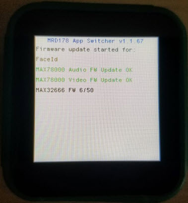
Selecting and loading a demo
If the SD car is not inserted, the App-Switcher displays an error message waits for the user to restart the MRD178. Press and holding the power button until the display turns off (12-15 seconds!). Insert the SD Card, then press the power button momentarily to restart.
Additional Information
Complete instructions on the updating firmware, using the App-Switcher and troubleshooting, as well as the demo firmware files, are available on our MRD178 GitHub project here: refdes/README.md at main · MaximIntegratedAI/refdes (github.com)
Documentation & Resources
-
MAXREFDES178 Design Files3/1/2023ZIP12 M
Support & Training
Search our knowledge base for answers to your technical questions. Our dedicated team of Applications Engineers are also available to answer your technical questions.