Powering a Dust Mote from a Piezoelectric Transducer
Increasing the level of remote monitoring and control of industrial environments—such as factories, plants and refineries—enables process engineers and managers to see the overall health of a system or factory, ultimately improving decision making. The easiest way to increase monitoring and control coverage is to use Dust Networks® SmartMesh® wireless sensor networks, which enable easy installation in remote environments. SmartMesh sensors and controllers are often deployed in locations where electrical power connections are not readily available. For this reason, using energy harvesting technology as the source for powering these sensors is attractive.
The LTC3330 is a nanopower buck-boost DC/DC with energy harvesting battery life extender technology that can be attached to a piezoelectric transducer to provide energy to power a Dust Networks mote. The LTC3330 integrates a high voltage step-down energy harvesting power supply plus a buckboost DC/DC converter powered by a primary cell battery to create a single output always-on power supply that sources power for the remote Dust mote.
When vibration energy is available, the LTC3330 uses this as its source of power rather than the battery. For short periods when vibration energy isn’t available, the LTC3330 charges and balances a supercapacitor that can be called on to support the load. The LTC3330’s combination of energy harvesting and supercapacitor charging/balancing circuitry can extend the life of the primary cell battery by several orders of magnitude, resulting in significantly fewer maintenance calls to replace batteries (with the savings multiplied by the number of installed sensors/controllers).
Interfacing the LTC3330 With the Dust Mote
Figure 1 shows the LTC3330 with an output supercapacitor, a Dust mote attached, a battery installed and EH_ON connected to OUT2. In this configuration, when EH_ON is low, VOUT is set to 2.5V and when EH_ON is high, VOUT is set to 3.6V. A Midé V25W piezoelectric transducer is mechanically attached to a vibration source, and its electrical contacts are connected to the AC1 and AC2 pins of the LTC3330. The vibration source produces 1gRMS of force at a 60Hz acceleration, which produces an open circuit voltage of 10.6VPEAK. Figure 2 shows the input capacitor being recharged from the V25W piezoelectric transducer. The input capacitor charges from 4.48V to 5.92V in 208ms. The power delivered from the V25W is 648µW.

Figure 1. Dust mote setup with a supercapacitor, a battery and EH_ON connected to OUT2
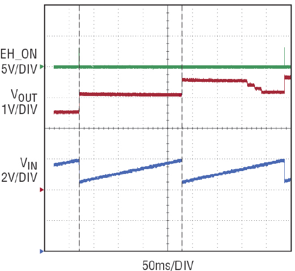
Figure 2. Midé V25W charging the 18µF input capacitance from 4.48V to 5.92V in 208ms
The 22µF capacitor is only 18µF at the applied voltage of 5.0V, so every VIN_UVLO_RISING and FALLING event produces 26µC of charge that can be transferred to the output minus the efficiency (90%) of the buck regulator within the LTC3330. Figure 3 shows the charging of the output supercapacitor to 3.6V with the Midé V25W transducer. It takes approximately 3300 seconds for the output supercapacitor to charge to 3.6V.
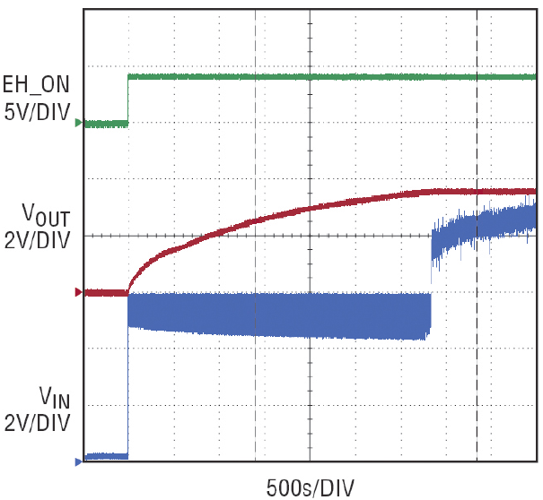
Figure 3. Midé 25W charging output supercapacitor to 3.6V
In Figure 1, when EH_ON is low, VOUT is set to 2.5V and when EH_ON is high, VOUT is set to 3.6V. The first marker in Figure 4 indicates where the vibration source is activated; VIN rises above the VIN_UVLO_RISING threshold. EH_ON goes high causing VOUT to rise toward 3.6V (VOUT starts at 2.5V because the battery has charge). As EH_ON goes high, PGVOUT goes low, since the new VOUT level of 3.6V is not yet reached. As the charge on VIN is transferred to VOUT, VIN discharges and when VIN reaches its UVLO_FALLING threshold, EH_ON goes low, causing the targeted VOUT to again be 2.5V.
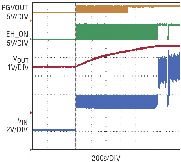
Figure 4. Midé 25W charging output supercapacitor from 2.5V to 3.6V
Given that the output capacitor is very large and the average load is less than the input power supplied by the Midé piezoelectric transducer, the output voltage increases to the higher set point of 3.6V over many cycles. During the transition from the BAT set point of 2.5V to the energy harvester set point of 3.6V, VOUT is above the 2.5V PGVOUT threshold, hence, PGVOUT goes high every time EH_ON goes low. This cycle repeats until VOUT reaches the PGVOUT threshold for the VOUT setting of 3.6V.
Figure 5 shows the discharging of VOUT when the vibration source is removed and VIN drops below the UVLO_FALLING threshold causing EH_ON to go low. The supercapacitor on VOUT will discharge down to the new target voltage of 2.5V at which point the buck-boost regulator will turn on supplying power to the Dust mote. The discharging of the supercapacitor on VOUT provides an energy source for shortterm loss of the vibration source and extends the life of the battery.
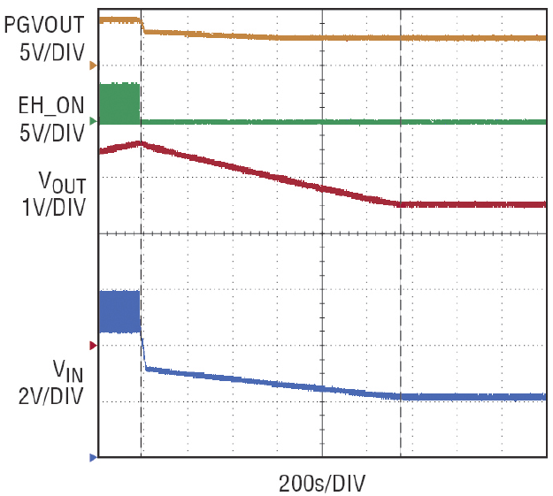
Figure 5. Output supercapacitor discharging when the vibration source is switched off
Conclusion
The LTC3330 provides a complete solution for powering a Dust Networks mote from a vibration source using the Midé V25W piezoelectric transducer and a primary cell battery connected to the BAT pin. The V25W piezoelectric transducer supports output power requirements from a vibration source, thus extending the life of the battery. When combined with a supercapacitor attached to VOUT, the LTC3330 enables even longer extended battery life, reducing maintenance calls to replace batteries.
关于作者
关联至此文章
产品
{{modalTitle}}
{{modalDescription}}
{{dropdownTitle}}
- {{defaultSelectedText}} {{#each projectNames}}
- {{name}} {{/each}} {{#if newProjectText}}
-
 {{newProjectText}}
{{/if}}
{{newProjectText}}
{{/if}}
{{newProjectTitle}}
{{projectNameErrorText}}
最新视频 20