摘要
Transmission of power and data on long coaxial cable bundles in automotive requires protection from various short-circuit modes (STG, STB). Remote cameras are small and require space- and power-efficient solutions. For each challenge, we propose solutions that not only meet the stringent requirements for automotive quality and reliability, but are power-efficient and occupy a small PCB space. The MAX20039 buck-boost converter is an effective supply for power-over-coax. The MAX20087 quad power camera protector is a compact, efficient protection IC. The dual MAX20019 cascade buck converter configuration delivers high efficiency in a small space. This triplet of ADAS ICs effectively provides power and protection to the path from the car battery to the remote cameras.
Introduction
Modern cars are loaded with sensors aimed at making the driving experience safe and accident-free. Cameras are a big part of the advanced driver assistance system (ADAS) toolset, providing views of blindspots previously unavailable to the driver, traffic sign recognition, pedestrian detection, and aiding with vehicle parking (Figure 1). All these sensors located strategically along the vehicle periphery need electric power to operate.
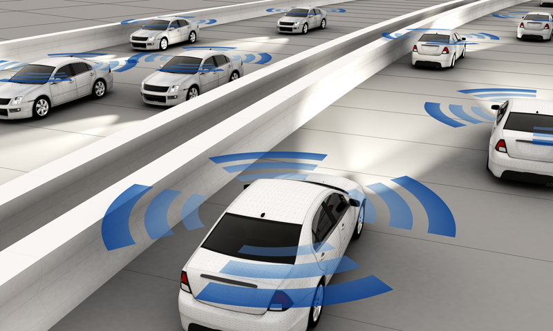 Figure 1. The intelligent highway environment.
Along the power path from the car battery to the remote cameras, there are many challenges. The front-end regulator interfacing with the car battery must support cold crank and start/stop while withstanding "load dump" and meeting ASIL B-D safety specifications. The current and voltage going into the camera modules via the coaxial cables must be monitored and controlled for various types of faults. The remote camera modules, with their on-board power management systems, must be small, efficient, and cost-effective.
This design solution reviews the full power management path, from car battery to remote cameras, and proposes a system-level solution to meet the power path challenges of size, efficiency, and safety.
Remote Camera System
Figure 2 shows an example of a surround-view camera system. Here a buck-boost converter connects to the battery and provides DC power to the remote cameras through a quad protector IC, a bank of AC-blocking coils (L), and four coaxial cables. A quad deserializer connects the microprocessor to the remote cameras via the bank of AC-coupling capacitors (C) and the same coaxial cables.
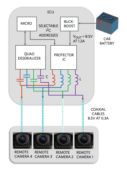 Figure 2. Surround-view camera system.
Single-Channel Power Path
A power management section of a single channel is highlighted in Figure 3. The buck-boost converter interfaces with the battery, while the protector IC protects from various fault conditions that may occur along the coaxial cable. On the remote camera module, two dual-buck converters power the imager and the serializer.
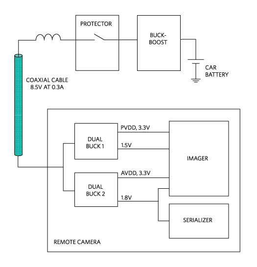 Figure 3. Remote camera single-channel detail.
In the following sections, we will discuss each element in the power chain.
Buck-Boost for Start/Stop and Cold Crank
Internal combustion engine cars can save as much as 10% in fuel consumption by shutting down the motor when the car is idle. The car battery is typically at 13.5V but can be as high as 16V on a fully charged battery. Vehicles that employ start/stop technology experience large voltage dips when the engine starts, so the power source lower limit can be well below the typical 13.5V and can often be 6V or even lower.
Cold crank is an even more severe condition incurred by internal combustion engines. In cold weather, the car battery voltage at the start of the engine can dip as low as 5V or lower. It is worth noting that electric cars do not have to deal with either problem.
A buck-boost converter keeps its output in regulation in the presence of wide input voltage swings above and below its output. Figure 4 shows the buck-boost power train architecture and its operation table. For VIN > VOUT, the IC regulates in buck (step-down) mode, while for VIN < VOUT, it seamlessly transitions to boost (step-up) operation ensuring that the VOUT output remains in tight regulation and is glitch-free. The entire battery voltage range is covered in a switch-mode, high-efficiency fashion.
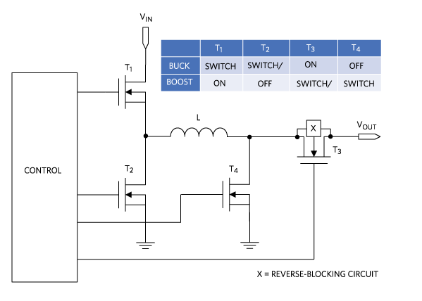 Figure 4. Buck-boost power train architecture and operation table.
STG and STB Protection
In vehicles, some of the most common problems with the cables and wires that extend throughout the car are the damage to the wires themselves and the accidental connection to the vehicle ground or main battery supply.
Connecting to ground is potentially dangerous because devices on the wire can produce significant power that gets dumped into the vehicle ground, potentially causing them to overheat and break if they don't have built-in protection. Connecting to the battery supply line is also potentially dangerous, an electrical device that is meant to run at only 5V can suddenly be connected to a source with a higher-than-permissible voltage. This can cascade to an even worse situation where the device gets damaged by the car battery, then draws a lot of power because the batteries can produce hundreds of amperes. It is not outside the realm of possibility for things to explode.
In automotive terms, an accidental connection to ground or battery is called “short-to-ground" (STG) or "short-to-battery" (STB), respectively. The STB protection prevents an overvoltage on the outputs. The STG protection limits the device sink/source current that results from the short circuit.
It is important to protect against STG and STB directly on the front-end of the battery power source. Safety features on the front-end help to protect all downstream circuitry from damage.
Integrated Buck-Boost Converter
A suitable buck-boost converter will integrate both control and four DMOS power transistors with low RDS(ON) and high efficiency within a small package.
The IC must meet the most stringent automotive quality and reliability requirements. Output disruptions due to input voltage variations can be minimized by the regulator’s fast line-transient response. As an example, in Figure 5, a positive input transient from 3.5V to 13.5V causes a deviation of only +50mV on a 5V output, with only 22µF on the output! Conversely, in Figure 6, a negative input transient also only produces a -50mV deviation on the output. A fast load-transient response will help minimize the size of the output passives. The IC should also be 40V load-dump tolerant.
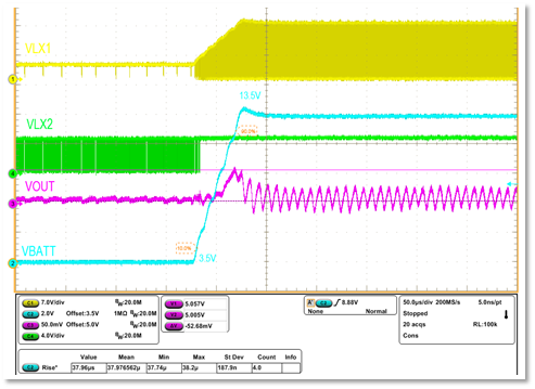 Figure 5. Positive line-transient response.
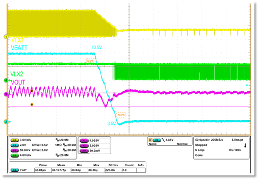 Figure 6. Negative line-transient response.
Small PCB Size
In the example of Figure 7, thanks to a high level of integration and a small TQFN-20 (4mm x 4mm) package, the entire buck-boost function is confined to a small area of 277mm2.
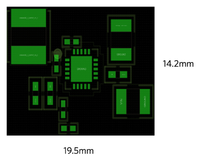 Figure 7. Buck-boost converter PCB area (277mm2).
Output Protection
The quad power camera protector IC in Figure 8 limits the load current to each of the four output channels. Each output is individually protected from STB, STG, and overcurrent conditions. The low RDS(ON) of the two back-to-back DMOS transistors assures low power dissipation, while a small package helps reduce PCB size. The IC should be equipped with an enable input and an I2C interface to read the diagnostic status of the device. An on-board ADC enables the reading of the current through each switch. The ASIL B-D compliant versions will include support for reading additional diagnostic measurements through the ADC, ensuring higher-fault coverage.
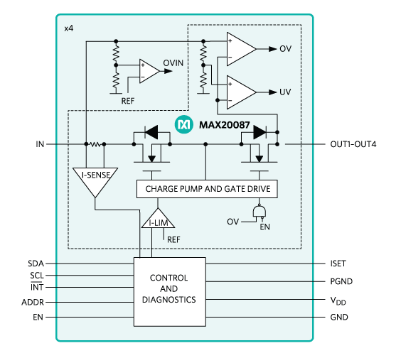 Figure 8. Input current and voltage protection.
Remote Camera Power
The remote camera modules, with their on-board power management systems, must be small, efficient, and cost-effective. The integration of two buck converters for cascaded operation, both working at or near full load, and a high duty cycle is ideal for this application (Figure 9). By covering the four remote camera rails with two cascaded dual-buck converter ICs, we save space and preserve efficiency. Further details about this solution can be found in a related design solution article.
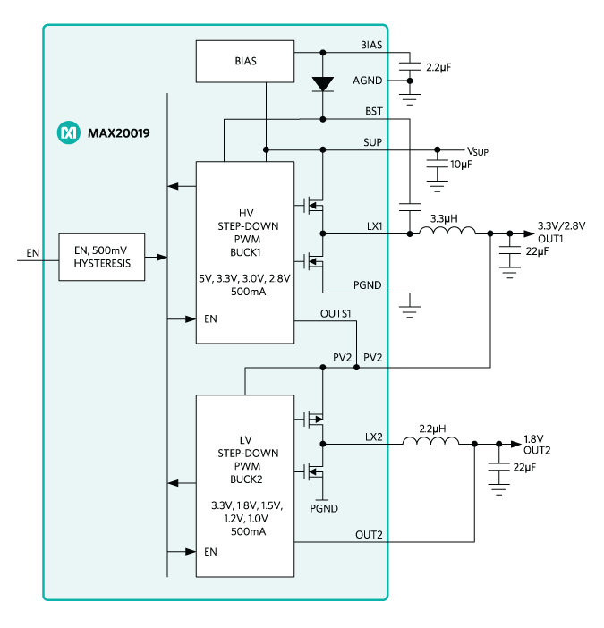 Figure 9. Dual buck converter cascade.
Conclusion
Along the power path from the car battery to the remote camera there are several technical challenges. At the interface with the battery we have severe line transients induced by load dump, start/stop, and cold-crank operation. Transmission of power and data on long coaxial cable bundles requires protection from various short-circuit modes (STG, STB). Remote cameras are small and require space- and power-efficient solutions. For each challenge, we proposed solutions that not only meet the stringent requirements for automotive quality and reliability, but are power-efficient and occupy a small PCB space. The MAX20039 buck-boost converter is an effective supply for power-over-coax. The MAX20087 quad power camera protector is a compact, efficient protection IC.
The dual MAX20019 cascade buck converter configuration delivers high efficiency in a small space. This triplet of ADAS ICs effectively provides power and protection to the path from the car battery to the remote cameras.
关联至此文章
产品分类
{{modalTitle}}
{{modalDescription}}
{{dropdownTitle}}
- {{defaultSelectedText}} {{#each projectNames}}
- {{name}} {{/each}} {{#if newProjectText}}
-
{{newProjectText}}
{{/if}}
{{newProjectTitle}}
{{projectNameErrorText}}


