摘要
Maximizing the linearity of a power amplifier should not come with the caveat of excessive power consumption or increased system complexity in telecommunications equipment. In this design solution, we consider the suitability of three different linearization techniques for deployment in 5G telecommunications infrastructure, while bearing in mind these constraints.
Introduction
“Everything is linear if plotted on a log-log scale with a fat magic marker.” This so-called ‘Mar’s Law’ presents a tongue-in-cheek perspective on how data measurements can sometimes be manipulated to fit a more linear profile than is the reality. However, there are no such shortcuts to achieving high linearity for a power amplifier (PA), which is at the heart of mobile cellular communication infrastructure. The unfolding deployment of 5G or 5th generation cellular mobile communications (Figure 1) will place further demands on the performance of these amplifiers.
 th generation cellular mobile communication." class="img-responsive">
Figure 1. 5th generation cellular mobile communication.
In this design solution, we present the features and benefits that 5G telecommunications technology promises to bring and the associated demands that it will place on PA designs. We then review the most commonly used PA linearization techniques, assessing their suitability to meet these demands before presenting a low-power linearizer IC with the potential to greatly simplify PA designs while also reducing their power consumption in 5G applications.
5G Design Challenge
5G promises to offer several advantages over incumbent telecommunications technologies. It will provide higher data rates for more concurrent users, while also extending the battery life of mobile devices. To realize this, PAs must operate with the highest possible efficiency and at a higher bandwidth (up to 100MHz) than is currently required.
Amplifier Linearity
A perfectly linear PA should only generate an amplified version of a wanted input signal. In reality, such a PA does not exist. Instead, nonlinearity causes the output signal to be distorted, with the amount of distortion increasing as the amplifier approaches its saturation point (Figure 2).

Figure 2. Relationship between output power and distortion.
For a multi-tone input signal, nonlinearity causes unwanted intermodulation frequencies to appear at the output of the PA (Figure 3).
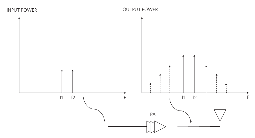
Figure 3. Intermodulation terms generated by the PA.
Reducing PA distortion requires the use of some form of linearization technique. In the following sections, we discuss the operation and suitability of the most common linearization techniques, within the context of 5G.
Backoff
Limiting the maximum output power level so that the entire signal is within the linear region of the PA transfer curve is a technique commonly referred to as “backoff.” A disadvantage of this relatively straightforward approach is that the amplifier’s efficiency (the ability to convert DC supply power into RF energy) decreases as the PA operating point is further backed off from its saturation point. The amount of backoff required to meet the signal peak-to-average ratio (PAR) required for some systems can reduce the efficiency of the PA to as low as 8%. This results in higher power consumption, higher cost of system implementation, and a much bigger heatsink. Therefore, backoff is not a suitable linearization approach to achieve acceptable efficiency in 5G applications.
Active Linearization
Improving PA linearity without reducing efficiency requires a form of active linearization called “predistortion.” With this technique, the amount of distortion caused by the inherent nonlinearity of the PA is “predicted” and its inverse is injected into signal path, reducing the magnitude of the unwanted tones, relative to the wanted signal at the amplifier output (Figure 4). This is specified as the adjacent channel leakage ratio (ACLR) and should be at least -50dBc.
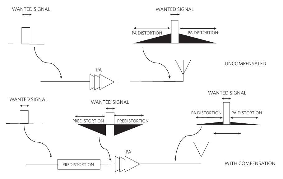
Figure 4. PA output characteristics with predistortion linearization.
Two commonly used types of active linearization are digital predistortion (DPD) and radio frequency power amplifier linearization (RFPAL).
DPD
As illustrated in Figure 5, digital predistortion (DPD) adds the predistortion correction signal to the desired signal at the earliest point in the signal chain, namely the digital baseband.
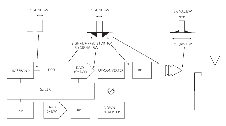
Figure 5. Digital predistortion system implementation.
DPD systems can be implemented in several ways. While fully integrated versions (incorporating baseband, digital, and RF) are available, some solutions have a separate digital baseband with discrete RF. Yet another variation consists of an FPGA with an RF transceiver (and a DPD observation path). However, the requirement for the transceiver to work at a frequency of 5 times the input signal bandwidth greatly increases design complexity, footprint, and power consumption (5W typical), making DPD an unsuitable linearization technique to use in small, low-power applications.
RFPAL
Figure 6 below shows a high-level block diagram of a system using an alternative active linearization predistortion technique called RFPAL.
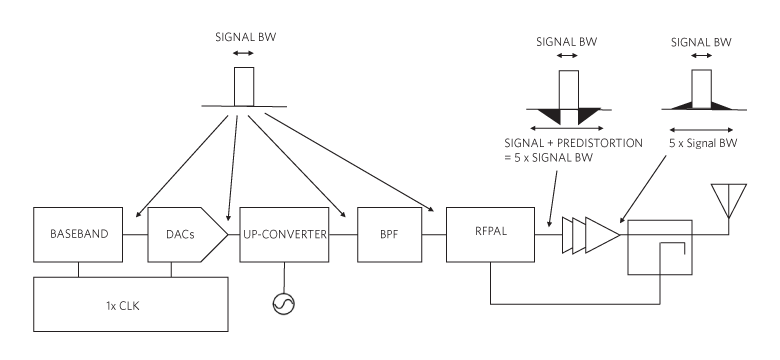
Figure 6. RF predistortion system implementation.
Using a standalone RFIN/RFOUT architecture and adaptive RF predistortion technology, this approach allows the correction signal to be injected only at the point it is needed, namely the PA's input. This means that the system can operate at a lower frequency (the input signal bandwidth) using a much simpler and smaller transmitter and baseband architecture, requiring less power than DPD systems. Until recently, the maximum linearized input-channel bandwidth using RFPAL was only 60MHz. Figure 7 shows a new RFPAL IC which overcomes this limitation.
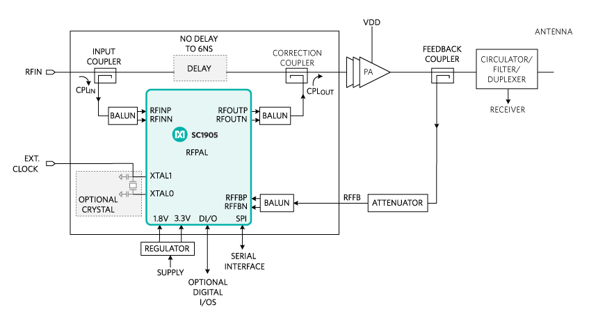
Figure 7. SC1905 RFPAL typical application circuit.
With an operating frequency range up to 3.8GHz, this product has a linearized input signal bandwidth of up to 100MHz. Consuming only 1280mW, it lowers power consumption by up to 70% compared to DPD solutions. Figure 8 shows the measured ACLR and efficiency performance (five non-contiguous 20MHz LTE channels, 10dB PAR) for a typical PA using this linearizer.
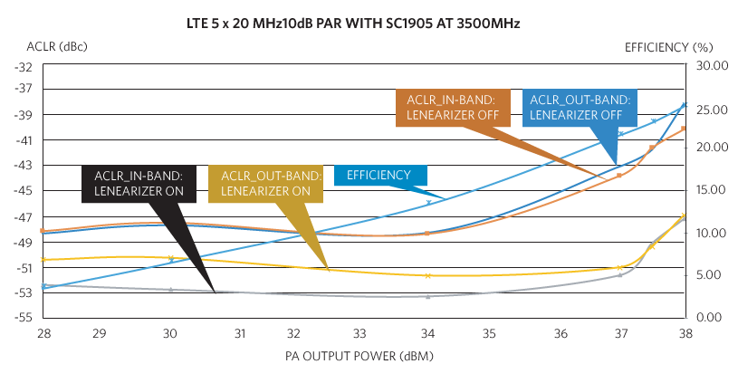
Figure 8. ACLR for PA using SC1905 RFPAL.
For an output power level of 37dBm, the efficiency of the PA is 23% at -50dB ACLR (an ACLR improvement of ~8dB without RFPAL). Additionally, since this RFPAL device has been evaluated with several popular PAs (including Class A, Class AB and Doherty), it effectively represents a “plug-and-play” solution, reducing design complexity, cycle duration, and risk. The IC is available in a 9mm x 9mm QFN package resulting in a total solution size (including power supply, heatsink, and enclosure) of only 6.5cm2. Additionally, the linearized PA signal can be upconverted using a mixer for applications up to 6GHz, if required.
Conclusion
5G telecommunications equipment will be required to operate at higher bandwidths and with greater efficiency than ever before. The linearity and efficiency of the PAs used will be key to meeting these requirements. In this design solution, we have considered some of the most common PA linearization techniques. We have shown that backoff is not suitable for use in 5G designs but using DPD as a form of active linearization improves overall linearity and efficiency. However, it is a highly complex technique, resulting in increased overall system power consumption and bigger solution size. We can conclude that a simpler, lower power form of linearization can be achieved using a small, plug-and-play RFPAL IC, which increases PA efficiency for an input signal bandwidth up to 100MHz. It is suitable for use with PAs of different architectures (Class A/AB/Doherty), processes (GaAs, GaN, InGa), and frequencies (698MHz to 3.8GHz) across a range of applications. This makes it the best option for 5G wireless cellular infrastructure and other applications.
A similar version of this design solution originally appeared in Power Systems Design on November 01, 2019.
关联至此文章
产品
{{modalTitle}}
{{modalDescription}}
{{dropdownTitle}}
- {{defaultSelectedText}} {{#each projectNames}}
- {{name}} {{/each}} {{#if newProjectText}}
-
 {{newProjectText}}
{{/if}}
{{newProjectText}}
{{/if}}
{{newProjectTitle}}
{{projectNameErrorText}}
最新视频 21


