Minimize Standby Current in Automotive DDR Supplies
When you turn on a laptop or a smart phone, you expect to wait for it to boot up, but you are less patient when you turn on your car. With a car, consumers expect immediate access to computer electronics, including navigation and infotainment systems, and automobile manufacturers strive to meet this desire with design strategies that shorten start-up time. One such strategy is to keep dynamic memory (RAM) active at all times, even during the ignition-off state.

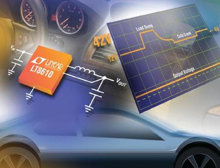
The LT8610 Keeps Automotive Electronics Running.
The DDR3 memory used in automobiles operates on a 1.5V rail with peak load currents over 2A—preferably produced by a high efficiency DC/DC converter to minimize heat dissipation. In these applications, light load efficiency is just as important to preserve battery life when the automobile is not running. DDR memory can consume 1mA - 10mA from the 1.5V rail in standby, but drawing 10mA from the battery is unacceptable when the car is parked for long periods. This constraint rules out the use of a linear regulator, where input and output current are equal. On the other hand, a switching step-down (buck) regulator draws less input current than load current in proportion to the step-down ratio:
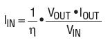
where n is the efficiency factor (0 to 1). Figure 1 shows that the LT8610AB synchronous step-down regulator achieves ~83% efficiency at a 1mA load. For a battery voltage of 12V and load current of 1mA at 1.5V, calculated input current is only 151μA.

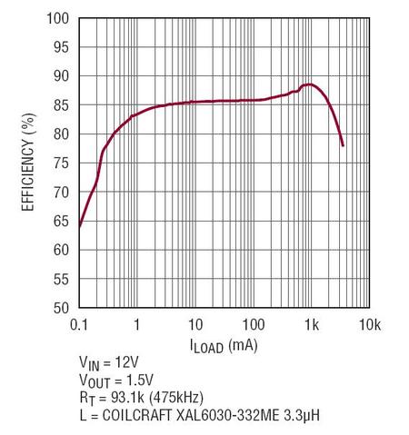
Figure 1. LT8610AB efficiency vs. load.
Direct DC/DC Conversion From Car Battery To 1.5V DDR Memory
LT8610A and LT8610AB are monolithic, synchronous step-down regulators designed specifically for automotive systems. They deliver 3.5A while consuming only 2.5μA quiescent current. Building a circuit around them is easy. No additional semiconductors are required, they work with inexpensive ceramic capacitors, and the MSOP package has leads that are easy to solder and inspect. With a typical minimum on-time of 30ns (45ns guaranteed maximum), one can design compact, high switching-frequency buck regulators with large step-down ratios. Figure 2 shows an application that delivers 3.5A at 1.5V. The operating frequency is 475kHz to optimize efficiency and remain below the AM radio band.


Figure 2. This LT8610A or LT8610AB step down converter circuit accepts automotive battery and generates 1.5V at 3.5A. Low quiescent current and synchronous rectification result in high efficiency across the entire load range.
Both parts feature excellent fault tolerance to automotive environments. A maximum input of 42V handles load dumps. A robust switch design and high speed current comparator protect the device during output shorts. The minimum input is worst-case 3.4V, the maximum duty cycle is above 99% and the dropout voltage is typically 200mV at 1A, all of which keep the output in regulation through cold-crank. The typical minimum input voltage is plotted in Figure 3.

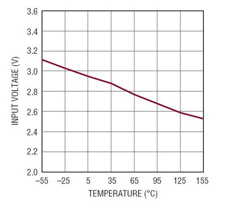
Figure 3. Keeping the memory alive in cold crank or start-stop events. The LT8610A and LT8610AB operate down to a typical minimum input voltage of 2.9V at 25°C, with 3.4V maximum guaranteed over temperature.
Save The Battery With Low Ripple Burst Mode Operation And Minimal Quiescent Current
The LT8610A and LT8610AB are designed to minimize output voltage ripple over the entire load range. At light loads, they maintain efficiency by reducing their operating frequency and entering Burst Mode operation. Fast transient response is maintained even at very low loads. This feature combined with the very low quiescent current of 2.5μA means that, even at a few μA of load, the LT8610A and LT8610AB are more efficient than a linear regulator with zero quiescent current. For systems where low frequency operation must be avoided, Burst Mode operation can be turned off by applying either a logic high signal or clock signal to the SYNC pin. The difference between the LT8610A and LT8610AB is that the LT8610AB features higher efficiency at light loads. This is achieved by using an increased Burst Mode current limit, allowing more energy to be delivered during each switch cycle and lowering the switching frequency for a given load. Because a fixed amount of energy is required to switch the MOSFET on and off, a lower switching frequency reduces gate-charge losses and increases efficiency.
Figure 4 shows the efficiency difference between the LT8610A and LT8610AB. For loads between 1mA and 100mA, the LT8610AB improves efficiency by more than 10% compared to the LT8610A. The trade-off to the increased Burst Mode current limit is that more energy is delivered in each switch cycle, so more output capacitance is required to keep output voltage ripple low. Figure 5 compares the output ripple for the LT8610A and LT8610AB as a function of the output capacitance for two inductor values, at 10mA load. In addition to the current limit, the inductor choice affects the efficiency and switching frequency in Burst Mode operation. This is because for a fixed current limit, a larger inductor value can store more energy than a smaller features one. If high efficiency at light loads is paramount, then the inductor value can be increased beyond the starting value recommended in the data sheet.

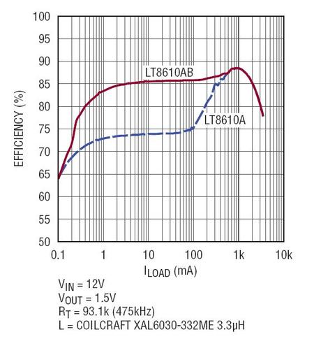
Figure 4. An increased Burst Mode current limit on the LT8610AB results in substantial efficiency gains at light load compared to the LT8610A.

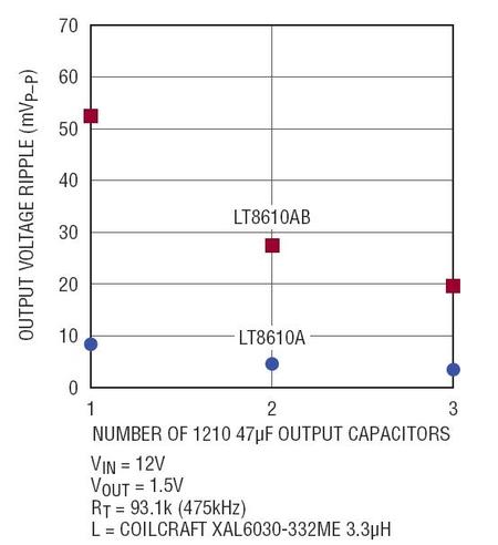
Figure 5a. Output voltage ripple versus number of 1210 size 47μF output capacitors for two inductor values, at 10mA load. Ripple for the 475kHz application in Figure 2.

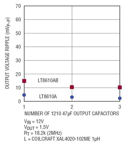
Figure 5b. Output voltage ripple versus number of 1210 size 47μF output capacitors for two inductor values, at 10mA load. Ripple for the 2MHz application in Figure 6.
Go Faster For A Smaller Solution
For most automotive systems, 9V to 16V is the typical input voltage, so application circuits are usually optimized for this range. The 475kHz application in Figure 2 operates at the designed frequency over the entire input range of 3.5V to 42V. However, if we restrict the normal operating voltage to 16V (42V transient), the operating frequency can be increased and the value and size of the inductor reduced. With a worst-case minimum on-time of 45ns, the LT8610A and LT8610AB can be programmed to 2MHz as shown in Figure 6.
Note that when the input voltage goes above 16V, the output remains in regulation although the switching frequency decreases to maintain safe operation. The 2MHz solution is identical to the circuit in Figure 2, except for the RT resistor changed to 18.2kΩ and the inductor value and size reduced in order to save space. Figure 7 shows efficiency versus load for two inductor choices.

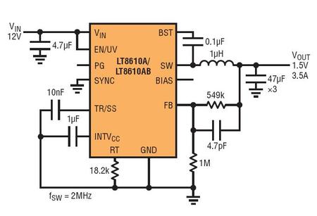
Figure 6. Similar 12V to 1.5V application as in Figure 2, but the operating frequency of the LT8610A and LT8610AB is increased to 2MHz for reduced inductor value and size.

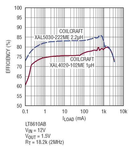
Figure 7a. LT8610A efficiency vs. load at 2MHz with two inductor values.

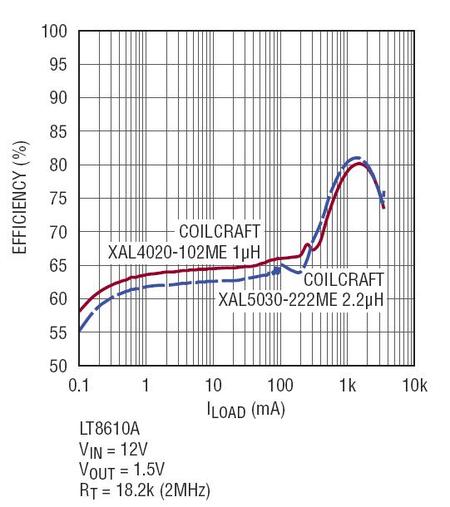
Figure 7b. LT8610AB efficiency vs. load at 2MHz with two inductor values.
Bias Pin Optimizes Efficiency
The LT8610A and LT8610AB use two internal nMOSFETs specifically optimized for automotive applications. In particular, the gate drive circuitry requires less than 3V to fully enhance the FETs. To generate the gate drive supply, the LT8610A/AB includes an internal linear voltage regulator, the output of which is the INTVCC pin (do not load INTVCC with external circuitry).
An important feature is that this internal regulator can draw current from either the VIN pin or the BIAS pin. If the BIAS pin is left open, then gate drive current is drawn from VIN. However, if a voltage of 3.1V or higher is tied to the BIAS pin, gate drive current is drawn from BIAS. If the BIAS voltage is lower than VIN, the internal linear regulator will run more efficiently using the lower voltage supply, thus increasing overall efficiency.
The efficiency data in Figures 1, 4 and 7 was recorded with the BIAS pin open. After all, if the 1.5V output is the only rail alive, then there is likely no good place to tie the BIAS pin. However, if there is a 3.3V or 5V supply, tie it to the BIAS pin, even if the supply is not available in standby or ignition-off conditions. Figure 8 shows the efficiency with and without a 3.3V supply connected to BIAS. In calculating the total efficiency, we have included the power drawn from the 3.3V rail and assumed that it was generated with 85% efficiency.

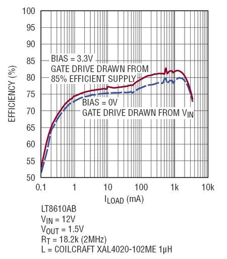
Figure 8a. LT8610AB Efficiency can be increased if the BIAS pin is tied to an external 3.3V supply. (External supply efficiency of 85% is assumed and factored into overall efficiency shown here.)

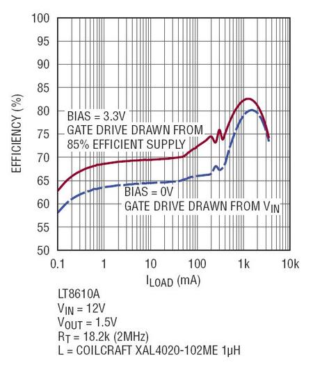
Figure 8b. LT8610A Efficiency can be increased if the BIAS pin is tied to an external 3.3V supply. (External supply efficiency of 85% is assumed and factored into overall efficiency shown here.)
Note that the benefit to externally powering BIAS is greater at higher operating frequencies because the gate drive current is higher. The LT8610A also benefits more from external bias compared to the LT8610AB—the AB’s increased Burst Mode current limit results in a lower operating frequency for a given load.
Not Just For Memory
The LT8610AB is an excellent regulator for other automotive supplies, including 3.3V and 5V supplies, with efficiency above 90%, as shown in Figure 9. An important consideration for automotive applications is the behavior of the power supply during cold crank and idle-stop transients, when the voltage from the 12V battery may drop below 4V. The LT8610AB operates up to 99% duty cycle, providing output regulation at the lowest possible input voltage. Figure 10(a) shows the dropout voltage. This is the difference between VIN and VOUT as the input voltage decreases towards the intended output regulation voltage. The LT8610AB also has excellent start-up and dropout behavior, resulting in predictable and reliable output voltage as a function of input voltage. Figure 10(b) shows the output voltage as the input supply is ramped from zero to 10V and back to zero.

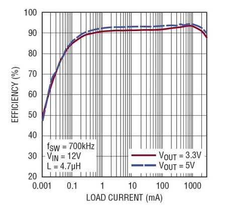
Figure 9. Efficiency for 3.3V and 5V outputs is above 90%, reducing total power dissipation and keeping temperature under control.

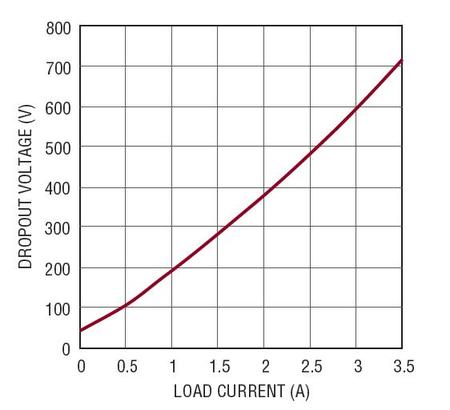
Figure 10a. The LT8610AB dropout voltage vs. load current.

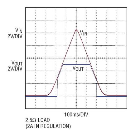
Figure 10b. The LT8610AB operates to 99% duty cycle, providing smooth start-up.
Conclusion
The LT8610A and LT8610AB have a low component count, low minimum input voltage, low quiescent current and high efficiency across a wide load range. These features make them the preferred solutions for providing standby power to DDR memory in automotive applications.
关于作者
{{modalTitle}}
{{modalDescription}}
{{dropdownTitle}}
- {{defaultSelectedText}} {{#each projectNames}}
- {{name}} {{/each}} {{#if newProjectText}}
-
 {{newProjectText}}
{{/if}}
{{newProjectText}}
{{/if}}
{{newProjectTitle}}
{{projectNameErrorText}}
最新视频 21