摘要
This application note describes how to recycle lithium-ion (Li+) batteries from older devices for use in other electronic devices, such as toys. This can all be done without the need for a microcontroller (or the required software). One challenge is that the battery charger in these older devices cannot usually be reused. The designer needs to create their own charger circuit, which this application note explains how to do in detail.
A similar version of this application note was published in Elektor magazine in June, 2013.
Introduction
It can be quite tricky to reuse lithium-ion batteries from discarded equipment since these cells are often charged inside the equipment. In other words, there is no separate charger that can be reused. Fortunately, it turns out to be fairly easy to build a charger for used (or new) lithium-ion cells.
Like most people, you probably have old devices lying around that use lithium-ion batteries for the supply. This type of battery has been used in most portable equipment produced in the last few years because it can be easily manufactured in various sizes and shapes, and it has a relatively large capacity (compared to NiMH and NiCd batteries).
What can you do with that old MP3 player or cell phone that's been replaced by a newer, better version? Usually the electronics cannot be used for any other purpose, but the battery can still be used, even for toys. Since electronics hobbyists tend to be an inventive lot, they will usually find a way to incorporate and recycle a battery. The author, for example, replaced three penlight cells in a Lego® train with a lithium-ion battery (see Figure 1).

Figure 1. Board with three penlight cells replaced by a single lithium-ion battery for use in a Lego train.
However, this still leaves the need to charge the battery. The original equipment usually contains a special charger circuit for the battery, most likely on a small part of the PCB. It is difficult to figure out which components are part of the charger circuit since no circuit diagram is normally made available for portable equipment. In that case, we will just have to build our own lithium-ion charger!
The Circuit
The charger circuit described in this article is built around a lithium-ion charger IC made by Maxim Integrated, the MAX8677A (see Figure 2). This IC works completely autonomously so there is no need for a microcontroller (and hence no software)! A number of LEDs are used by the MAX8677A to indicate the state of the charging process.
Figure 2. Block diagram of the internal circuit of the MAX8677A.
The MAX8677A is very flexible and features a Smart Power Selector™ topology (see Figure 3), which consists of three electronic switches that direct the charge and load currents according to the situation. With an external power source, the MAX8677A can use the available power to both charge the battery and supply the load. If the load requires more power than the charger can deliver, the MAX8677A can make the battery provide the extra current. When there is no external power source available, the load is powered solely by the battery.
The MAX8677A can be powered from a USB port via pins 15 and 16 (USB). In this case, the current drawn is limited to 500mA (the maximum for a USB 2.0 port). The IC can also be powered from an adapter via pins 2 and 3 (DC), where the current limit can be increased up to a maximum of 2A.
Figure 3. The Smart Power Selector technology splits the charge and load currents according to the demand.
For the charger circuit in this application note (Figure 4), we use the DC input, which gives us greater flexibility in setting the various limits. The operating voltage at the input is between 4.1V to 6.6V. If the voltage becomes too high, the MAX8677A turns off the input to prevent it from overheating. The IC can survive voltage spikes up to a maximum of 14V.
The charging status is provided by D1, D2, and D3. The following three states are indicated: the battery is being charged (LED D3), the battery is fully charged (LED D1), or the battery is faulty (LED D2).
Figure 4. The complete charger circuit consists mainly of the MAX8677A and a mini USB connector.
There are two current limits that can be set with this IC: one for the maximum charge current and one for the maximum input current. The second value should always be larger than the first. If this is not the case, the programmed maximum charge current can never be reached, as it cannot go higher than the maximum input current. Both these limits are set using a resistor.
Maximum charge current:
ICHGMAX = 3000/RISET = 3000/R9 = 3000/5.6kΩ = 535mA
Maximum input current:
IDCMAX = 3000/RPSET = 3000/R6 = 3000/3.3kΩ = 909mA
You can obviously select more suitable values depending on the power rating of the adapter, the power consumption of the device, and the desired load current. The MAX8677A can provide a maximum charge current of 1.5A.
We used a mini-USB connector, which makes it easy to power the circuit with contemporary mains adapters. This also ensures that we are using a 5V supply. The maximum input current should be adjusted according to the rating of the adapter. The circuit functions well when the adapter can provide a current of at least 1A.
Is There an NTC Thermistor?
Batteries are often provided with a negative temperature coefficient (NTC) thermistor, which is used to prevent the batteries from being charged at temperatures that are too high or too low. The battery, therefore, has three connections: a positive terminal (BAT+), a negative terminal (BAT-), and a connection for the NTC thermistor (see Figure 5). Note that some batteries with three connections have only a normal resistor inside that is used for identification. The value of the normal resistor will be constant and will not vary with the temperature of the battery.

Figure 5. Most lithium-ion batteries with three connections have an internal NTC thermistor connected as shown.
Referring back to Figure 4, when an NTC thermistor is used, it should be connected between the THM pin and ground (via the BAT- connection). A resistor (R7) is also connected between the THM pin and a reference voltage (VL), which creates a potential divider. The value of the resistor is chosen so that it has the same value as the NTC thermistor at a temperature of +25°C. The voltage at the THM pin at +25°C will be equal to 0.5 VL. When the temperature rises or falls, the resistance of the NTC thermistor falls or rises, as will the voltage at the THM pin. The device will only charge when this voltage is between 0.28 VL and 0.74 VL. With contemporary NTC thermistors, this corresponds to a temperature between 0°C and 50°C. When no NTC thermistor is available, you should add R8, which causes the voltage at the THM pin to be 0.5 VL.
Connection Tips
If you are reusing a cell-phone battery, it will already have a protection circuit by default, which protects the battery from overloading and being discharged too deeply. However, if you want to use a single cell, for example one taken from an old laptop battery pack, then you will have to make your own protection circuit. The circuit inside the pack will have been designed to protect the whole pack and can, therefore, not be used to protect a single cell.
A simple fuse (shown in Figure 4 as FS1, which is a surface-mount-device, or SMD, fuse on the PCB) offers sufficient protection from overloading, which means that separated cells are perfectly usable. However, a fuse does not offer any protection against deep discharging. When these types of cells are discharged too much, it is possible to damage them. This can happen when an ohmic load, such as a small incandescent light bulb, is attached for too long. However, most devices will stop working once the supply voltage has dropped below a certain value, which stops the cell from discharging further. Therefore, whether or not a fuse offers enough protection depends very much on the type of device that is connected.
Construction
For this project, we designed a compact PCB, which uses a large number of SMDs (see Figure 6). This design keeps the PCB very small, which makes it easier to build into the device. The board layout and the mask used to etch the PCB, both made using DesignSpark™ PCB, are available as downloads from the Maxim website.
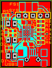
Figure 6. The PCB designed for this charger has been kept as small as possible to make it easier to build it into existing equipment.
In order to mount the SMDs, you will need some dexterity and soldering experience. For the TQFN-packaged MAX8677A, you should ideally use a reflow oven, since the pins and the exposed pad are on the underside of the 4mm x 4mm package. However, you can also solder the device by hand. Both will be described in the following sections.
Using a Reflow Oven
After using a reflow oven, you need to make the following connections. There are holes on the PCB for the connections to the LEDs, battery, and the load so they can be easily connected via wires. The mini-USB connector has two plastic pins that fit in the associated holes on the PCB, which align the socket. If you do not want to use the mini-USB connector, you can use these two holes for connecting the power. In that case, you have to make sure that the supply voltage is 5V.
Soldering a TQFN-Packaged MAX8677A by Hand
Mounting the MAX8677A with a hot-air soldering iron is possible if you are experienced enough, though a reflow oven makes life much easier. The method described here explains how to use an ordinary soldering iron to mount the device (see Figure 7), even though the homemade PCB does not have through-hole plating.

Figure 7. Steps in mounting the MAX8677A through hand-soldering a single hole.
Before etching the board, make sure that only the center hole in the exposed pad of the IC remains. The other surrounding eight holes can be removed from the design in the software, or you can use a felt pen to fill in the holes on the mask so they will not show up on the PCB.
- Drill a 1.5mm hole in the center of the exposed pad.
- Position the chip on the PCB.
- Solder all contacts along the sides of the chip. Use Litz wire to tidy everything up. (The author used a stereoscopic microscope to get a good view of everything.)
- When all contacts on the top side have been soldered properly, turn over the board and drop a few pieces of solder into the hole.
- Find a piece of solid copper cable that fits snugly in the 1.5mm hole and use a file to make one of the ends completely flat. Put this end through the hole and heat it using the soldering iron. At some point, the piece of copper wire becomes so hot that the pieces of solder in the hole start to melt. The copper wire will retract slightly and make contact with the exposed pad of the chip.
- Then solder the piece of wire to the ground plane on the solder side of the PCB.
You will now have a good electrical and thermal connection between the exposed pad of the chip and the ground plane on the solder side of the PCB.
Component List
The following table lists the components needed to populate the board.
| Designation | Description |
| Resistors (default: SMD0603) | |
| R1, R2, R5 | 4.7kΩ |
| R3, R4 | 560kΩ |
| R6 | 3.3kΩ |
| R7 | 10kΩ |
| R8 | 10kΩ (only if there is not an NTC thermistor in the battery) |
| R9 | 5.6kΩ |
| Capacitors (default: SMD0603) | |
| C1, C3 | 4.7µF (SMD0805) |
| C2 | 100nF |
| C4 | 68nF |
| Semiconductors | |
| D1 | LED, green, 3mm |
| D2 | LED, red, 3mm |
| D3 | LED, yellow, 3mm |
| IC1 | MAX8677AETG+ (24-pin TQFN) |
| Miscellaneous | |
| USB1 | Mini-USB connector, PCB mount, SMD (e.g., Molex® 67803-8020, RS Components #720-6618) |
| FS1 | Fuse, SMD, rating dependent on battery (e.g., LittelFuse® nano fuse 3A, Farnell/Newark #1596930RL) |
{{modalTitle}}
{{modalDescription}}
{{dropdownTitle}}
- {{defaultSelectedText}} {{#each projectNames}}
- {{name}} {{/each}} {{#if newProjectText}}
-
 {{newProjectText}}
{{/if}}
{{newProjectText}}
{{/if}}
{{newProjectTitle}}
{{projectNameErrorText}}
最新视频 20


