Hybrid Beamforming Transmit Calibration with SFDR Optimization
Abstract
Phased array calibration efforts are generally focused on optimizing the fundamental signal of interest. This article presents a method to further improve spurious performance once the phase calibration for the desired signal is known. Using this method, we will evaluate transmit spurious signals on a 32-element hybrid beamforming system comprised of four 8-element subarrays. The measurements shown demonstrate a greater than 25 dB performance improvement. To extend to larger systems, we include considerations for when a cancellation method is applicable vs. methods to ensure spurious signals are uncorrelated.
Introduction
For future phased arrays, there is a significant industry quest toward software-defined antennas. This brings a great desire for all-digital phased arrays to maximize antenna pattern programmability. In practice, particularly as frequency increases, the packaging, power consumption, and digital processing challenges force a reduction in the digital channel count. Hybrid beamforming provides the digital channel density relief often needed by implementation engineers and therefore will likely be around as a practical option for some time into the future.1
In large digital beamforming antennas, regardless of the architecture of hybrid vs. digital beamforming, dynamic range improvements through the beamforming process of combining signals from distributed waveform generators and receivers are highly desirable. A 10logN dynamic range improvement can be obtained in both noise and spurious performance if the associated error terms are uncorrelated. N in this case is the number of the waveform generator or receiver channels. Noise by nature is a random process and therefore lends itself well to tracking correlated and uncorrelated noise sources. However, forcing spurious signals to be uncorrelated is less obvious. Therefore, any design method that can force spurious signals to be uncorrelated is valuable to phased array system designers.
Various methods to force spurious decorrelation in phased arrays have been known for some time. Our first known publication dates to 2002,2 where a general method to ensure receiver spurious signals are uncorrelated is described. In the approach, signals are first modified in a known way across two receivers. Then the signals become distorted by the receiver’s nonlinear components. At the receiver output, the modifications introduced earlier in the receiver are inverted. The intended signals become coherent or correlated, but the distorted terms are not correlated. The modification method implemented in Howard (2002) was to set each local oscillator (LO) synthesizer to a different frequency, then correct for the modification by digitally tuning numerically controlled oscillators (NCOs) in the digital processing. Several other methods have also been published over the years.3,4 The method of offsetting LO frequencies was recently demonstrated and shown to be effective in test results from designs based on commercially available integrated transceivers.5,6 Recently, there has been published data on spurious improvements with distributed direct sampling RF data converters.7,8
In this work, we show that in a case where channels are well matched and a particular spurious frequency is inherently correlated across channels, the hybrid beamforming architecture lends itself to providing a method to not only force the spurious signals to be uncorrelated but to also be much more significantly improved through a cancellation approach. We also show the cancellation can be embedded in the calibration as the second step after the phase calibration in the array.
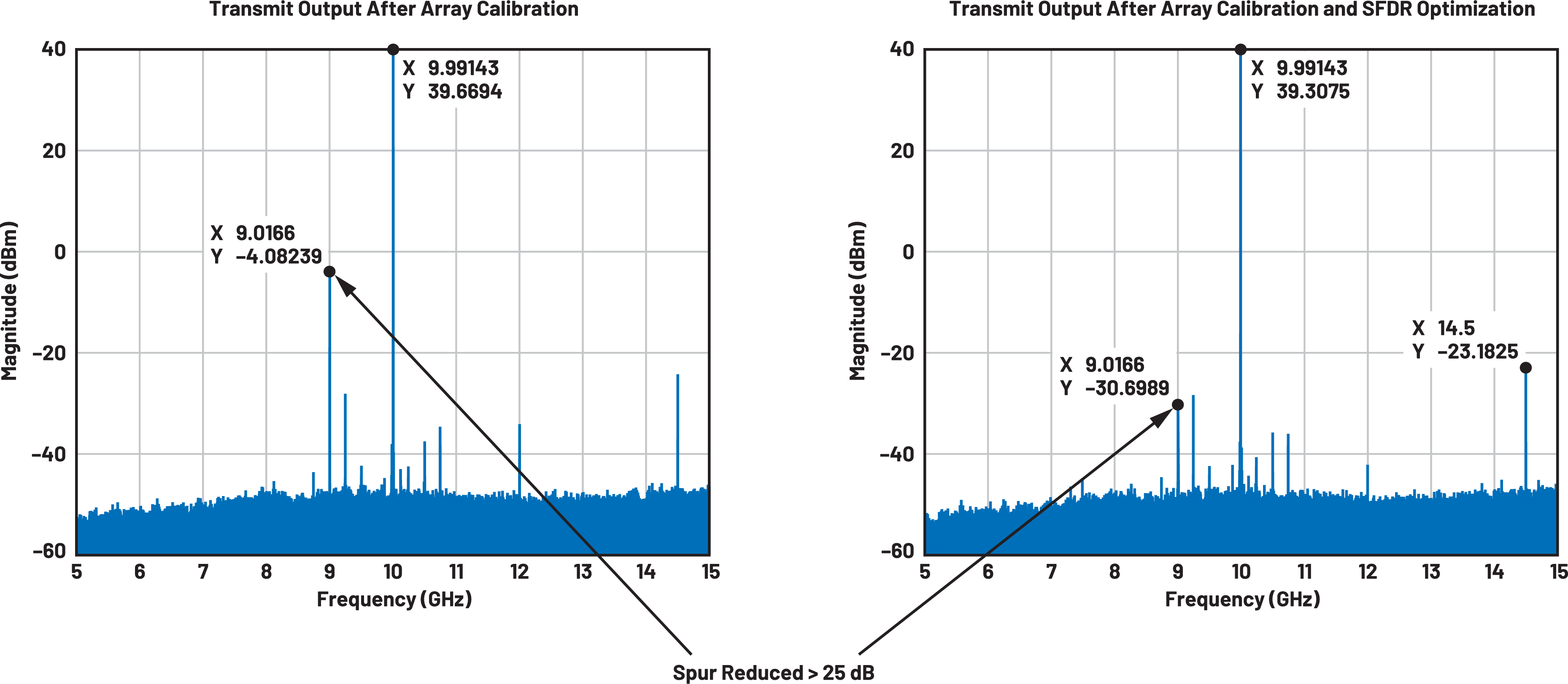
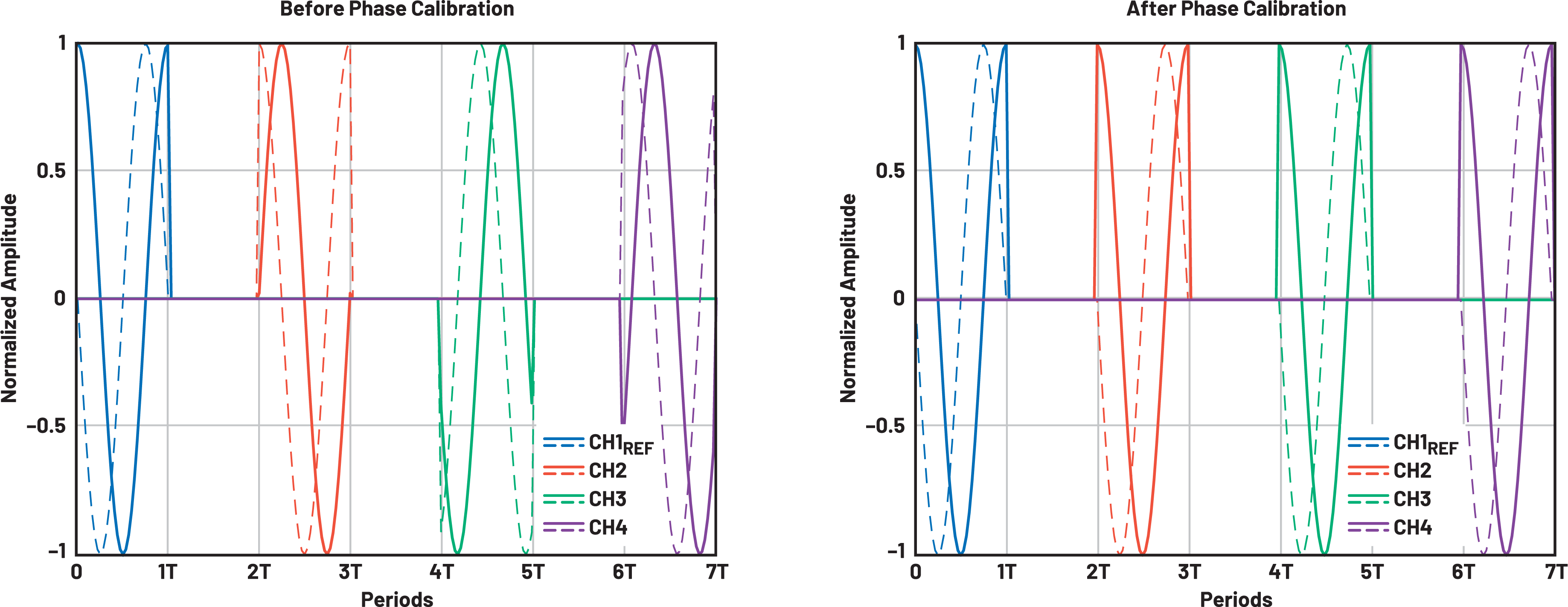
To illustrate the value of the approach, we introduce Figure 1. Here, measurements show >25 dB SFDR improvements from only four digital subarrays. Note the initial dominating spur is reduced significantly below other spurious signals. Spurious improvements of this magnitude from only four channels are much more than the standard 10logN improvement due to uncorrelated noise or spurious signals, and cancellation of the spurious signals has been demonstrated.

Combining Noise Voltages
When signals are combined either in free space or RF combining, the noise of each signal adds as

- c ranges –1 to +1
- –1 -> Cancels
- 0 -> Uncorrelated
- +1 -> Completely Correlated
- Spurs can be treated as a noise voltage
For phased arrays, the general goal for RF performance is a correlation coefficient of 0. This leads to array-level dynamic range improvements of 10logN where N is the number of channels. There are some specific cases where c can be a negative number and can create cancellation, and in this work, we demonstrate one example where cancellation can apply.
Consider if a particular mixing spur is found to be correlated across channels. In this instance, correlated means the mixing spur signals are matched in amplitude and phase across channels. If this condition exists, the hybrid beamforming architecture inherently provides the hooks to enable spur cancelling by finding an optimum phase rotation on both the direct digital synthesizer (DDS) and analog beamforming integrated circuit (BFIC) phase shifters to cancel the spurs.
Hardware Demonstrator Description
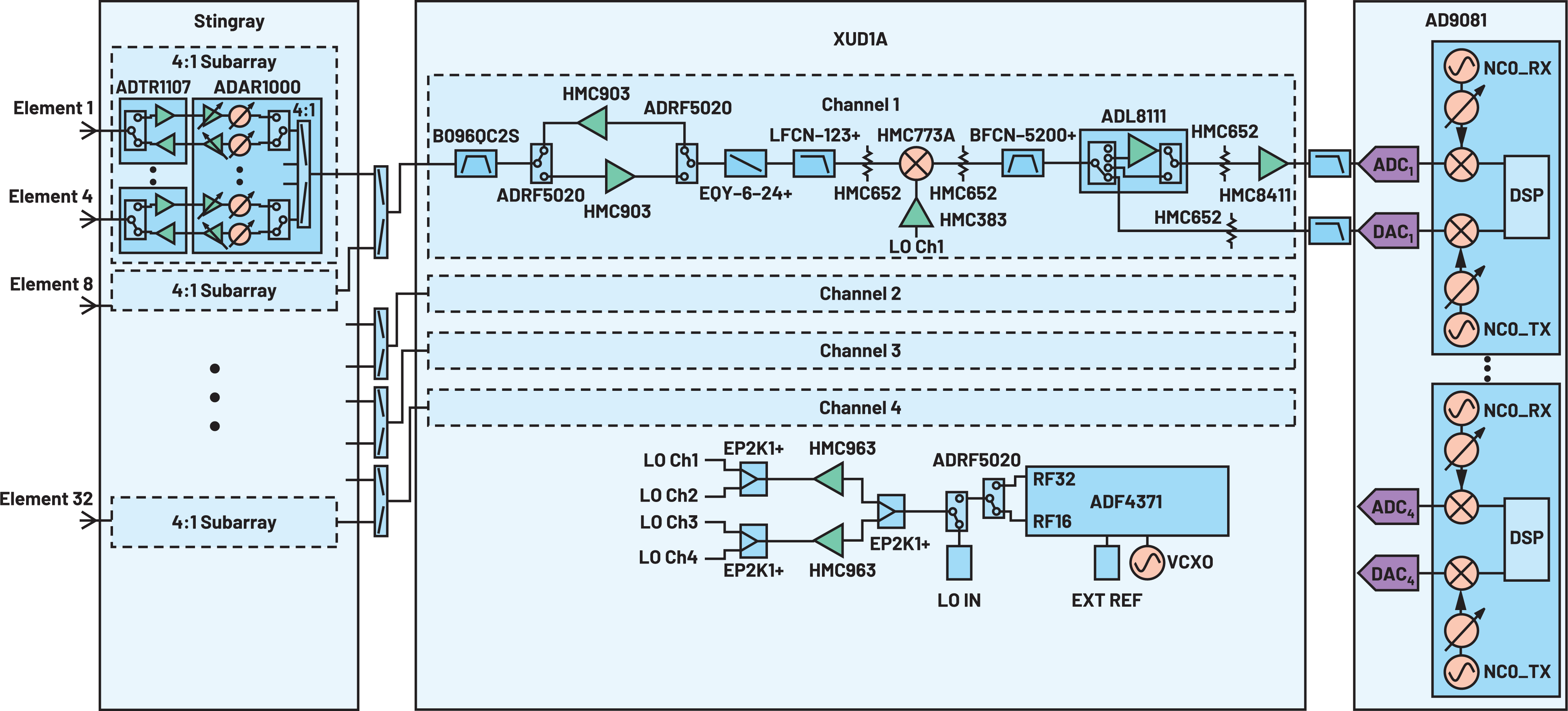
A 32-element hybrid beamforming prototype platform has been developed,9 and the detailed signal chain is shown in Figure 2.
The front end consists of 32 transmit/receive modules and eight analog BFICs. Two BFIC inputs/outputs combine to produce four 8-element subarrays. The four subarrays connect to a 4-channel microwave upconverter/downconverter. The 4-channel microwave upconverter/downconverter then connects to a digitizer IC that contains four analog-to-digital converters (ADCs) and four digital-to-analog converters (DACs). The ADCs sample at 4 GSPS whereas the DACs sample at 12 GSPS.
The microwave frequencies characterized are from 8 GHz to 12 GHz. The LO is set to a high-side LO with a fixed intermediate frequency (IF) centered at 4.5 GHz. At this IF frequency, the ADC is sampling in the third Nyquist zone.
A commercial FPGA board is used for data capture. A MATLAB® computer control interface has been developed enabling rapid waveform characterization in real hardware. The data analysis is performed with postprocessing in MATLAB.
Forcing Spurious Phase Rotation
Consider the spurious levels shown in Figure 1. The specific spurs and the spurious levels in dBc are shown in Table 1. The spurious levels are shown for each subarray, for the entire array with the initial calibration and the entire array after the additional SFDR calibration.
| Spurious Product | Subarray 1 (dBc) | Subarray 2 (dBc) | Subarray 3 (dBc) | Subarray 4 (dBc) | Full Array (dBc) Post Array Cal | Full Array (dBc) Post SFDR Optimization |
| 2IF | –43.6 | –46.1 | –43.8 | –41.7 | –43.7 | –70 |
| LO Leakage | –50.1 | –55.4 | –58.1 | –52.2 | –64.1 | –62.5 |
| DAC Clock | –68.7 | –66.8 | –69.2 | –65.1 | –71.9 | –81.7 |
| Spur 1 (9.24 GHz) |
–67.1 | –68.2 | –64.3 | –65.5 | –67.9 | –67.9 |
| Spur 2 (10.5 GHz) |
–72.5 | 73.3 | –72.9 | –74.8 | –77.3 | –75.3 |

Notice in this data, the 2IF spur is at the same level in each subarray. After the full array calibration, the combined data show the 2IF spur at the same dBc level with no improvement. This is an indicator that the 2IF spur is correlated across channels. This brings the question, “If the spur is correlated, then can the spur be forced to be uncorrelated?” A second question becomes, “If the spurs are so well correlated, then can they be forced to be canceled?”
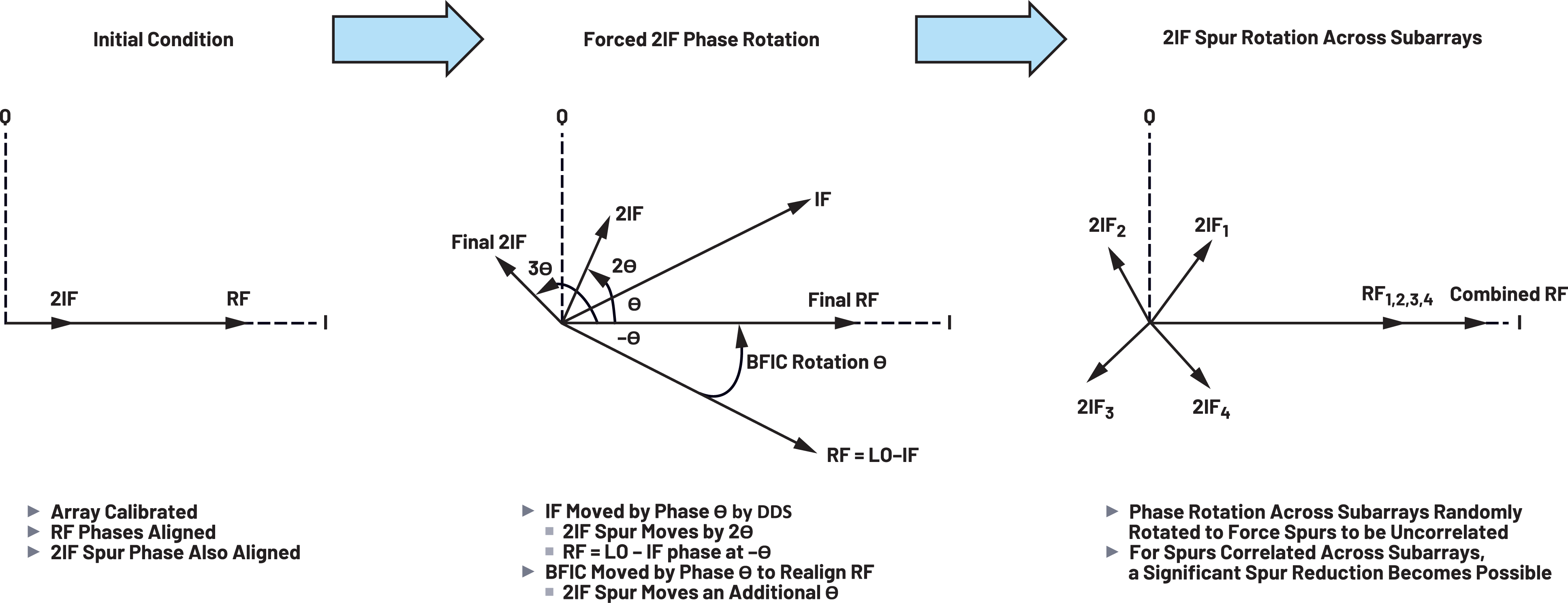
Figure 3 illustrates a method to visualize rotating the 2IF spur phase while maintaining the phase of the fundamental RF signal.
- First, assume the fundamental and the 2IF spur are both aligned in phase at 0°.
- If the phase of the IF frequency is rotated by a phase θ, then the 2IF frequency will rotate at twice this rate or 2θ. This can be controlled by the phase of the DAC output either by the NCO or the baseband IQ data.
- A high-side LO is used in this architecture. This causes the RF phase to rotate in the opposite direction of the IF phase so that the RF phase rotates by –θ. This means the analog BFIC phase shifters for the subarray all need to rotate by θ to realign the fundamental frequencies. This shift by the analog phase shifters causes an additional θ phase shift on the 2IF spur for a total phase shift of 3θ.
Figure 3 shows the principles that the 2IF spur can be rotated. The desired outcome is to find the appropriate rotation across each subarray such that the 2IF spur can be cancelled at the transmit output. We will show that the hybrid beamforming phased array architecture provides the necessary combination of IF phase control from the DDS frequency generation, and RF phase control through the subarray analog BFICs, to enable a built-in mechanism to rotate the relative phase of the 2IF spur across subarrays.
Transmit Calibration
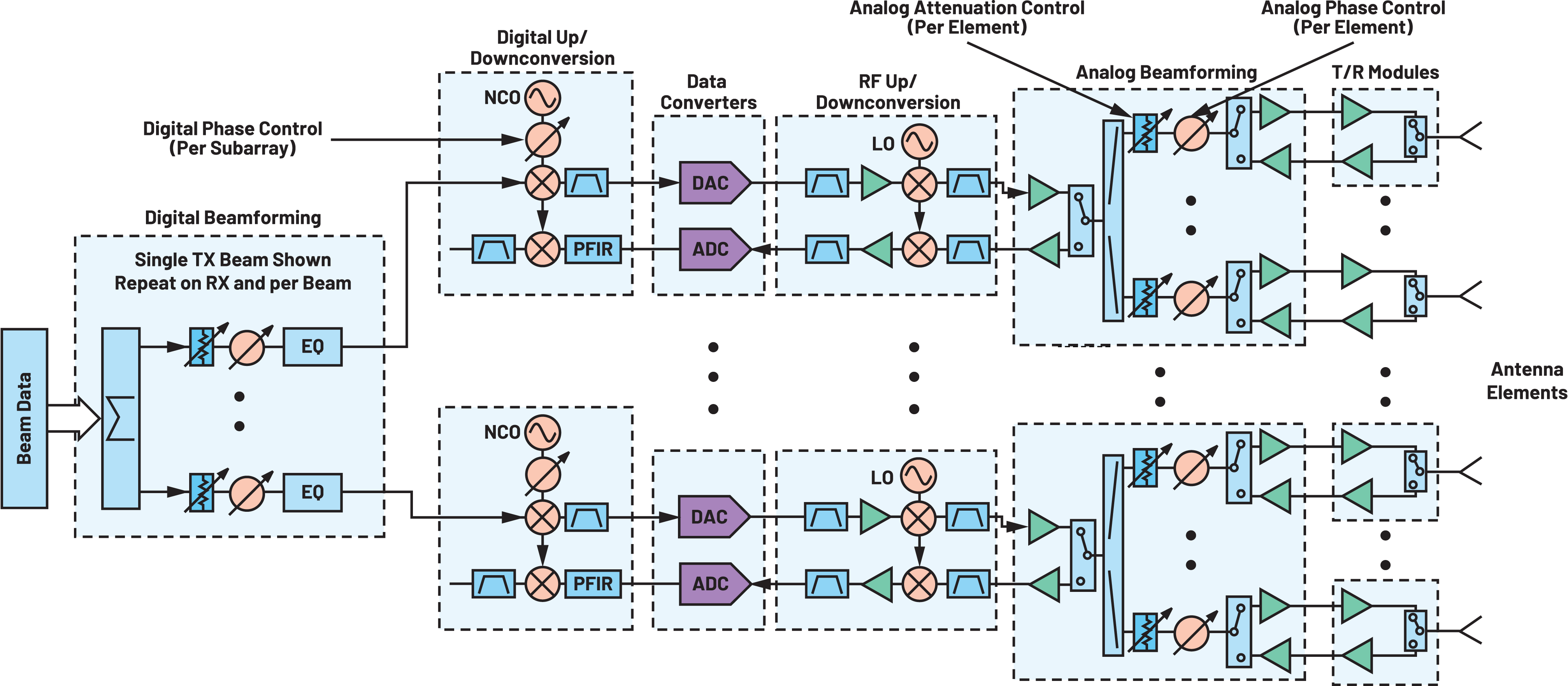
A generic hybrid beamforming architecture is shown in Figure 4 and described further in the study of Delos.8 Figure 4 also highlights the programmable amplitude and phase control used in the antenna calibration.
The calibration steps used to align the amplitude and phase of the hardware are discussed in this article.
Amplitude Calibration
The signal amplitude is measured for each channel and equalized to the lowest power channel. To simultaneously measure across subarrays, the frequencies are spaced out to enable measuring each subarray from a single spectrum analyzer measurement.
Phase Calibration
To enable simultaneous capture across subarrays, a time-interleaved pulsed calibration method is employed. Pulses are time interleaved per subarray. A pulsed continuous-wave (CW) signal is applied to a spectrum analyzer setup to offload in-phase (I) and quadrature-phase (Q) data. The spectrum analyzer is capable of a 160 MHz bandwidth in the IQ data mode. The transmitted center frequency is offset from the spectrum analyzer center frequency by 8 MHz to observe a full period in the IQ data. From this data, the phases across subarrays are matched. This concept is shown in Figure 5.

The phase alignment steps implemented are as follows:
Step 1: Align Element 1 across all four subarrays.
This is accomplished from a single data capture using time-interleaved pulses for each subarray with Element 1 enabled and the other elements disabled.
Step 2: Align elements 2 through 8 in subarrays 2, 3, and 4.
This is accomplished by seven pulsed data captures. In each data capture, the first pulse is from Subarray 1 Element 1, the remaining three pulses are for subarrays 2, 3, and 4, and each data capture steps through elements 2 through 8.
Step 3: Align elements 2 through 8 in Subarray 1.
This is accomplished by seven 2-pulse data captures. In each data capture, the second pulse is Subarray 2 Element 1, and the first pulse steps through Subarray 1 elements 2 through 8.
SFDR Optimization
The principles of the 2IF spur phase rotation are outlined in the Forcing Spurious Phase Rotation section. Next, we map this into an equation representation that allows a simpler translation into the software scripts used for the calibration.
First, we introduce the symbols used:

The output phase per element after the array calibration described in the Transmit Calibration can be written as:

Introducing additional SFDR phase optimization terms, the desired signal’s phase per element after the array calibration and SFDR optimization steps can be written as:

Similarly, this SFDR phase optimization step results in an output phase per element for the 2IF spur that can be written as:


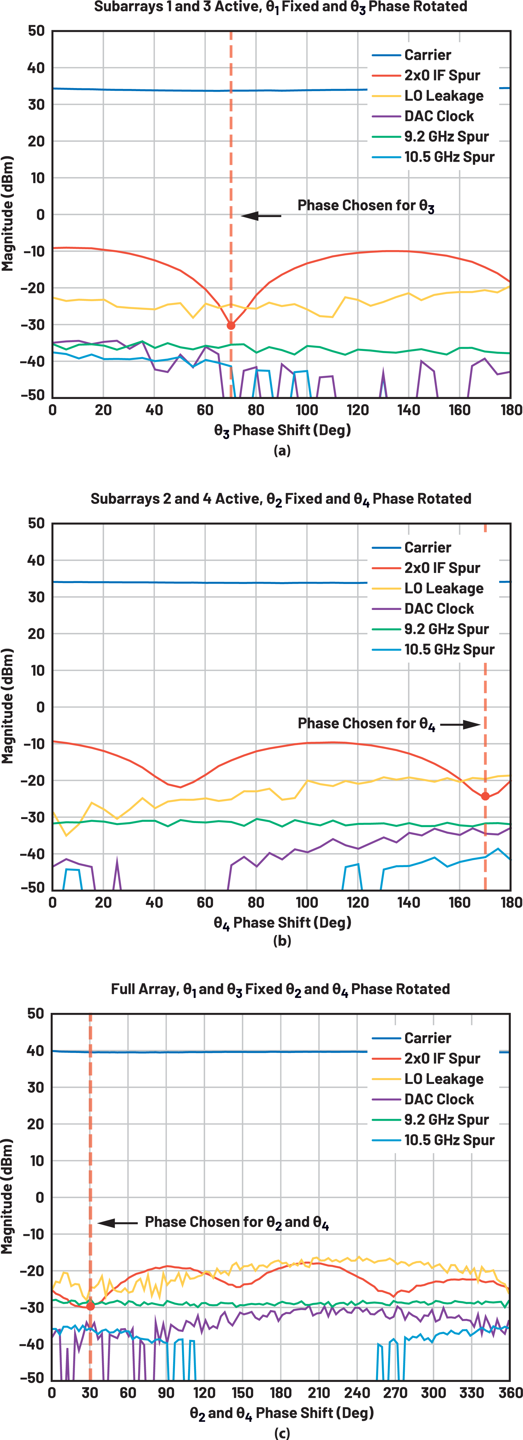
The SFDR optimization is accomplished in three steps shown graphically in Figure 6. The first step consists of activating half of the array and rotating the analog and digital phase of one subarray from 0° to 180° while keeping the other phase fixed at 0°. In this case, subarrays 1 and 3 are active while θ1 is kept fixed at 0° and θ3 is rotated while focusing on the magnitude of the 2IF spur. Figure 6a displays the phase shift of θ3 at which the 2IF spur is a minimum. Optimization Step 2 is performed in a similar fashion as Step 1, but with different subarrays active. For Step 2, subarrays 2 and 4 are active while θ2 is kept fixed at 0° and θ4 is rotated. The decided phase offset for θ4 is when the 2IF spur magnitude is at its minimum as shown in Figure 6b.
Lastly, the optimized phase offsets found in steps 1 and 2 are applied while all subarrays are active and a final phase rotation on two subarrays is executed. Figure 6c shows the results when θ1 and θ3 are kept at fixed values while θ2 and θ4 are rotated. Again, the optimal phase offsets are the corresponding minimum of the 2IF spur magnitude. It’s worth clarifying the final θ4 value is the sum of the phase offsets chosen in steps 2 and 3.
Validation Across Bandwidth
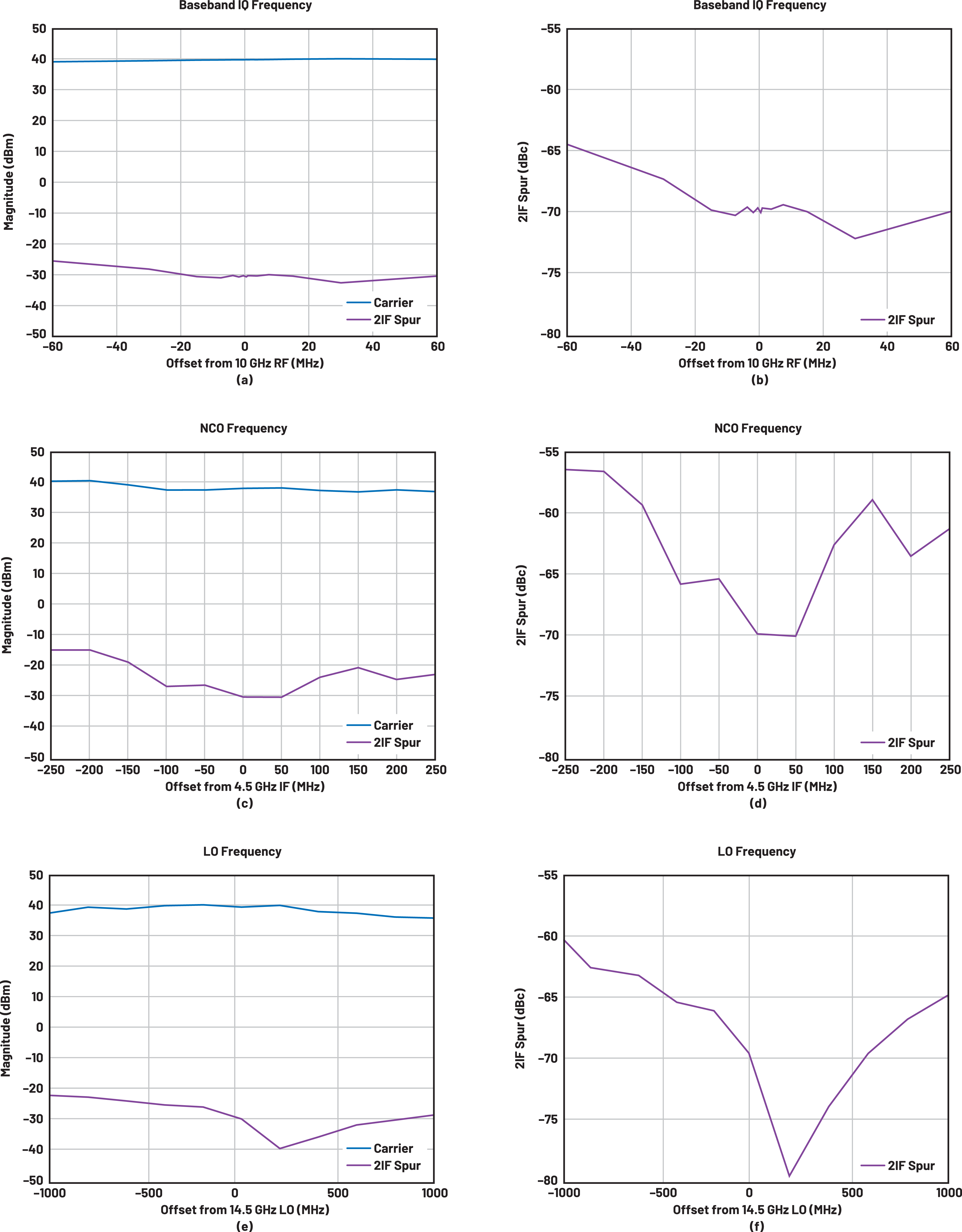
A concern whenever cancellation is implemented is to validate the cancellation holds across bandwidth and other conditions. In the hardware demonstrator used, there are three areas to consider: modulation on the baseband IQ data into the digitizer IC, changes in the NCO frequency in the DAC digital upconverter, and changes in the LO frequency. These results are shown in Figure 7. The IQ data is changed over a 100 MHz range, the NCO frequency is changed over a 500 MHz range, and the LO is changed over a 2 GHz range. In all cases, the 2IF spur holds to a significantly reduced level as compared to no SFDR optimization being implemented.
Spur Cancellation vs. Forcing Spurs to Be Uncorrelated
A perspective on spurious cancellation vs. a simpler decorrelation method and applicability to larger phased array systems is worth discussing.
In the case of this hardware, we demonstrate a spur cancellation method. This can apply to a single dominant spur if the spur of concern is shown to be correlated across the array. The optimization we described can be extended to larger arrays if the array is partitioned into smaller groups of subarrays for SFDR optimization or our method could be used as-is by splitting the array into quadrants.
There are many spurs in which cancellation becomes difficult. In this case, the 10logN improvement from ensuring the spurious signals are uncorrelated is more practical. For the case of many spurs or spurs that are not matched in amplitude, the SFDR phase randomization during the optimization step can be employed across the array to ensure spurious signals are uncorrelated and will still provide an improvement with this relatively easy software-level implementation.
Future Work
For phased arrays, a consideration not discussed yet is the effect of SFDR at angles away from the main beam of transmission. After the calibration and SFDR optimization steps, the spur reduction applies when the primary signals are all coherent or in the direction of the main beam. At off angles, there is a phase rotation of both the main carrier and the spurs. The SFDR optimization applied to reduce the SFDR in the direction of the main beam can cause the spurs to phase align in other angular directions. This effect will be evaluated as a follow up to this work.

Conclusion
The hybrid beamforming phased array architecture has natural hooks to force mixing spurs to be uncorrelated. The architecture provides phase shift control both in the analog phase shifters in the beamforming ICs as well as a phase control in the digital domain that can be either implemented with the baseband data or the NCO phase adjustment. The combination of these 2-phase control elements provides embedded phase control directly in the architecture that can be exploited to optimize SFDR performance as the second step after the first level of the phased array calibration. We have demonstrated this capability on commercially available hardware, described the optimization steps, and provided measured results.
关于作者
最新视频 21


