A Modern Solution to Evolving Smoke Safety Regulations
Introduction
This technical article provides a description of the software and data aspects of the CN-0537 smoke reference design that is designed and tested to meet the specifications outlined in UL 217, edition 8. It is designed by analyzing research fire data collected at the smoke testing facilities of Underwriters Laboratories (UL) and Intertek Group plc. These test facilities and the test procedure are in accordance with the UL 217 specifications for residential smoke alarms. The reference design uses the ADPD188BI integrated optical sensor (with LED and photodiode) along with an optimized smoke chamber designed to sense and measure smoke particles using a single calibrated device. Importantly, the reference design also includes a UL 217 tested and verified smoke detection algorithm to facilitate customers in reducing their product development life cycles and delivering their end product designs faster. The Arduino form factor-compatible reference design hardware, which includes the CN-0537 smoke detector reference design and ADICUP3029 microcontroller development board, is shown in Figure 1.

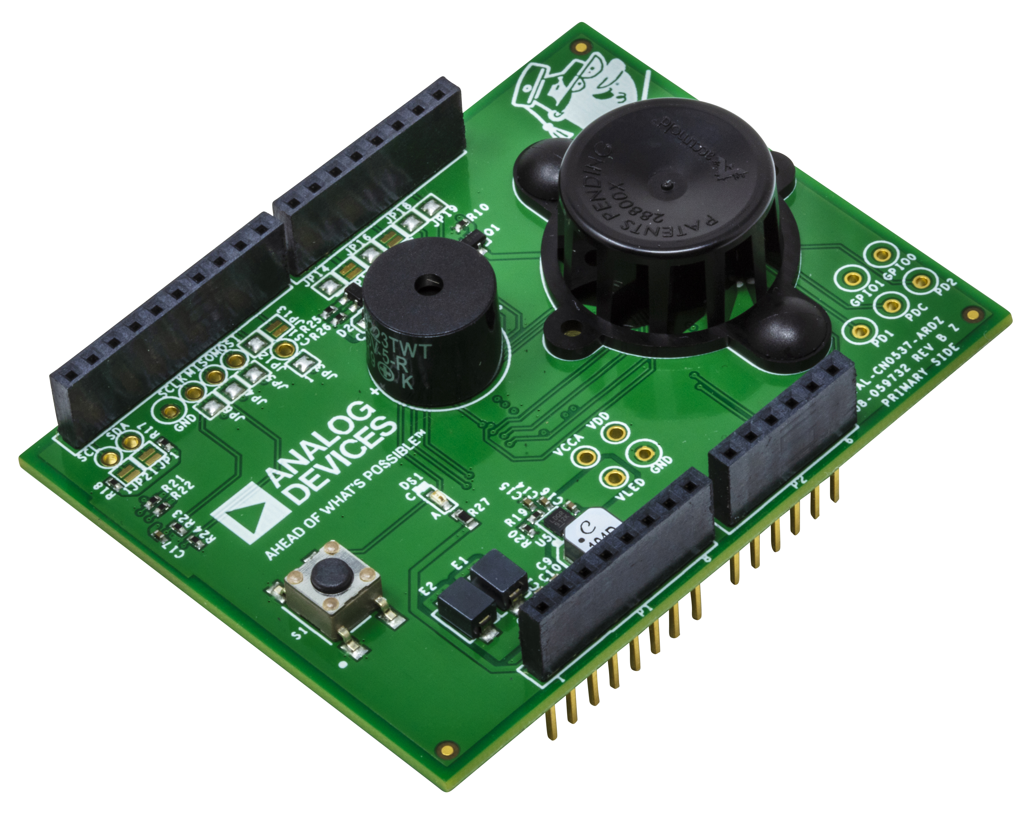
Figure 1. Smoke detector reference design hardware solution.
ADPD188BI Smoke Sensor
Since the 1970s, smoke detectors have become commonplace in commercial and residential buildings. Two basic types of detectors exist today—the ionization type, which uses radioactive matter to ionize the air and checks for an electrical imbalance; and the photoelectric type, which uses a light source aimed at an angle away from a photodetector and checks for photodetector current caused by the light reflecting from airborne particles to the photodiode.
Although a combined solution of both types is recommended, the photoelectric smoke detector is more popular due to its improved reliability in detecting common house fires and faster response times to smoldering fires.
The ADPD188BI optical module shown in Figure 2 is a complete photometric system specifically designed for smoke detection applications. Using the ADPD188BI in place of traditional, discrete smoke detector circuits greatly simplifies the design as the optoelectronics (consisting of two LEDs and two photodetectors) and the analog front end (AFE) are already integrated into the package. To perform smoke detection, the ADPD188BI utilizes a dual-wavelength technique: two integrated LEDs emit light at two different wavelengths; one at 470 nm (blue light) and the other at 850 nm (infrared light). These LEDs are pulsed in two independent time slots, and the transmitted light is scattered back onto the device by particulate matter in the air.

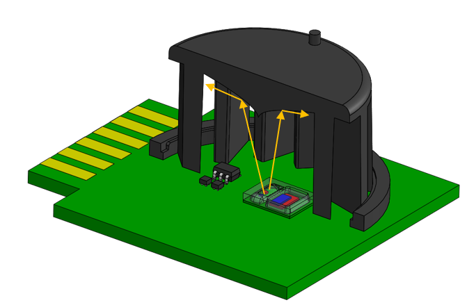
Figure 2. ADPD188BI and a cross-section of the smoke chamber.
Two integrated photodetectors then receive the scattered light and produce proportional levels of output current, which are converted internally by the AFE into digital code. Assuming the LED optical power is kept constant, an increase in ADPD188BI output values over time indicates a buildup in airborne particles, as illustrated in Figure 3.


Figure 3. Backscattering of light from ADPD188BI LEDs.
The smoke response of the ADPD188BI is best expressed as a ratio of the received optical power to the transmitted optical power. Referred to as the power transfer ratio (PTR), expressed in nW/mW, this parameter is a much more meaningful value than the raw output codes because it is independent of the actual hardware settings used. As for the steps involved in configuring the sensor to convert its output to PTR values, please refer to the application note available here.
LED Temperature Compensation
The response of the ADPD188BI is affected by the ambient temperature. For the blue channel, this is further complicated because the shape of the temperature response curve can also vary, depending on the amount of LED current used. For the infrared channel, the temperature response curve is independent of the LED current.
To determine the value of the relative response, the ability to measure the ambient temperature in real time is required. On the CN-0537, a temperature and humidity sensor monitors the conditions inside the chamber, next to the ADPD188BI. When selecting a sensor, the component size is the primary consideration because space is at a premium inside a chamber.
With the real-time temperature values inside the chamber, the temperature compensation is done in software by taking the relative response across the operating temperature of the part and multiplying it with the raw data read from the device. This gives us the temperature compensated data that can be used to calculate the PTR response. Relative response coefficients are kept in static tables in memory for the IR LED and the blue LED compensation data. After data is read from the device, the application reads the temperature sensor and the blue LED current to figure out which table and relative response coefficient is used. The table closer to the LED current level is used and the index value is calculated as:

where:
- index is the index to the appropriate element in the table
- temperature is current temperature
- granularity is the temperature difference between two data points in the relative response table; for example, if the ratios are 5° apart, the granularity would be 5
This method compensates the device data using zero-order interpolation in the relative response table. This is done for power and time efficiency. If higher accuracy is needed, granularity can be smaller and first- or second-order interpolation can be done, at the expense of power consumption and processor cycles.
Overview of UL 217 Standard and Test Scenarios
Similar to smoke detector technology, residential fire safety regulations have also remained virtually the same since the 1970s despite the advances in electronics and common household materials through the decades. New revisions in standards, such as ANSI/UL 217 and ANSI/UL 268, published by Underwriters Laboratory (UL), or the NFPA R 72 National Fire Alarm Code, published by the National Fire Protection Agency (NFPA), aim to address this gap by placing more complex requirements on modern smoke detector designs. UL 217 standard documents can be purchased from here.
For example, in addition to the traditional fire and smoke sensitivity tests, the latest edition of the UL 217 standard now requires smoke detectors to not produce a false alarm during nuisance events, like cooking. So modern smoke detectors must be able to distinguish between a cooking nuisance event and a fire event.
The goal of these new standards is to increase safety by decreasing the number of fire related deaths while reducing the number of false alarms that are generated from everyday activity. Traditionally, this would require a complicated solution with multiple sensor technologies and a level of artificial intelligence; however, the use of the ADPD188BI makes this significantly simpler to implement. The ADPD188BI is an integrated optical module with multiple LED sensors specifically designed for smoke detection.
For any smoke detector to become a commercial product, it must pass a certification. In the U.S., that is primarily UL 217. This specification highlights several test scenarios of fires or smoke events, which every unit tested needs to pass. An updated version of this specification will take effect in 2021, which will require additional tests to be passed, thus making it more difficult to receive certification.

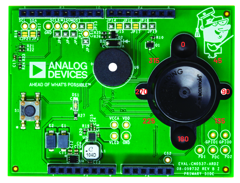
Figure 4. Physical orientation sensitivity tests of CN-0537.
Sensor detection performance is determined from two main test categories: sensitivity tests and scenario-based tests. Sensitivity tests focus upon the variance of the alarm triggers from different physical orientations and environmental conditions. An example of one of these tests is from Section 42 of UL 217, where smoke is fed into a chamber at a common rate and the alarm time and obscuration level are measured. This is repeated for eight orientations of the device and across multiple units. An example device is shown in Figure 4, where all eight smoke approach perspectives are labeled. These measurements cannot exceed 50% variation between the most and least sensitive units across all perspectives. To make this test even more difficult, the same units are also tested at temperature extremes and humidities to verify they maintain their consistency.
Scenario-based testing involves different fire sources as well as different constraints applied to different tests.
| Fire Source | Alarm Time Spec. | Alarm Obscuration Spec. |
| Smoldering Wood | Before 10%/foot | |
| Smoldering PU | Before 12%/foot | |
| Hamburger | Not before 1.5%/foot | |
| Paper | Less than 4 minutes from test start | |
| Flaming PU | Less than 4 minutes from test start | Before 5%/foot |
| Hamburger and PU | Less than 4 minutes from test start | Not before 1.5%/foot |
Under UL 217 8th edition, a new aspect was introduced to add nuisance sources with the traditional fire sources. This prevents simple threshold setting against smoke levels, since alarms would be prematurely triggered in such a scenario. An example of this scenario is shown in the smoke profile of Figure 5, where an initial peak is observed and a second ramping trend is seen. This is the profile of a nuisance plus valid smoke source, where a nuisance fire is modeled initially followed by a true fire condition where an alarm is meant to be raised. Based on the specifications mandated by UL 217, qualified detectors will not alarm until after the smoke has reach an initial level, L1, but before a specified amount of time, T1, has occurred and a certain smoke level, L2, has not been reached. These combined factors create an alarm window from these requirements. These requirements are also different between test fire sources, but must be handled by the same device without knowledge of a source fire. A summary table of these scenarios is provided in Table 1.


Figure 5. Testing perspective of CN-0537.
CN-0537 Smoke Detection Algorithm Design Methodology
Research Fire Data Collection
In order to correctly model both part variation and test variation, ADI designed and built PCBs with four and eight ADPD188BI smoke sensors mounted on the surface along with the necessary cabling to an MCU to facilitate data collection. All except one sensor was equipped with a chamber during each smoke test.
As a result, many sensors were tested across as many fires as practical at UL’s and Intertek’s test facilities. Consequently, each trial corresponding to any one of the smoke sources identified by UL 217 for certification is recorded by multiple boards and by multiple smoke sensors simultaneously. An illustration of the ceiling at Intertek’s smoke testing facility showing the PCBs mounted with ADPD188BI smoke sensors is provided in Figure 6. The general layout of the test facility depicting various components of the overall test setup is shown in Figure 7. Note that pods 1, 2, and 3 are located on the ceiling, whereas pods 4 and 5 are located on the walls.


Figure 6. ADPD188BI PCB pods mounted to the ceiling for UL 217 smoke testing.

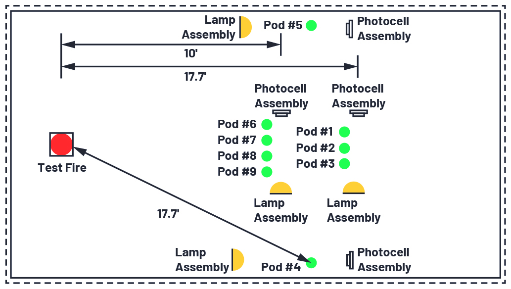
Figure 7. UL 217 compliant smoke testing facility layout.
Understanding Research Fire Data
We now look at certain key features present in a typical smoke profile observed in the event of a (hamburger) nuisance test fire. These features serve as signatures in isolating the smoke source, thereby aiding the design of the smoke detector algorithm
In the case of the nuisance fire shown in Figure 8, UL 217 mandates that the nuisance fire is extinguished when the corresponding obscuration reference reaches 1.5% and subsequently, upon starting a polyurethane (PU) fire, an obscuration reference can be collected using the beam located 17' away. This is visible from Figure 8, where around the 1100 second mark, the response of both the blue LED and IR PD begin to droop due to the nuisance fire being extinguished. From that point on, the response is entirely due to the PU fire.

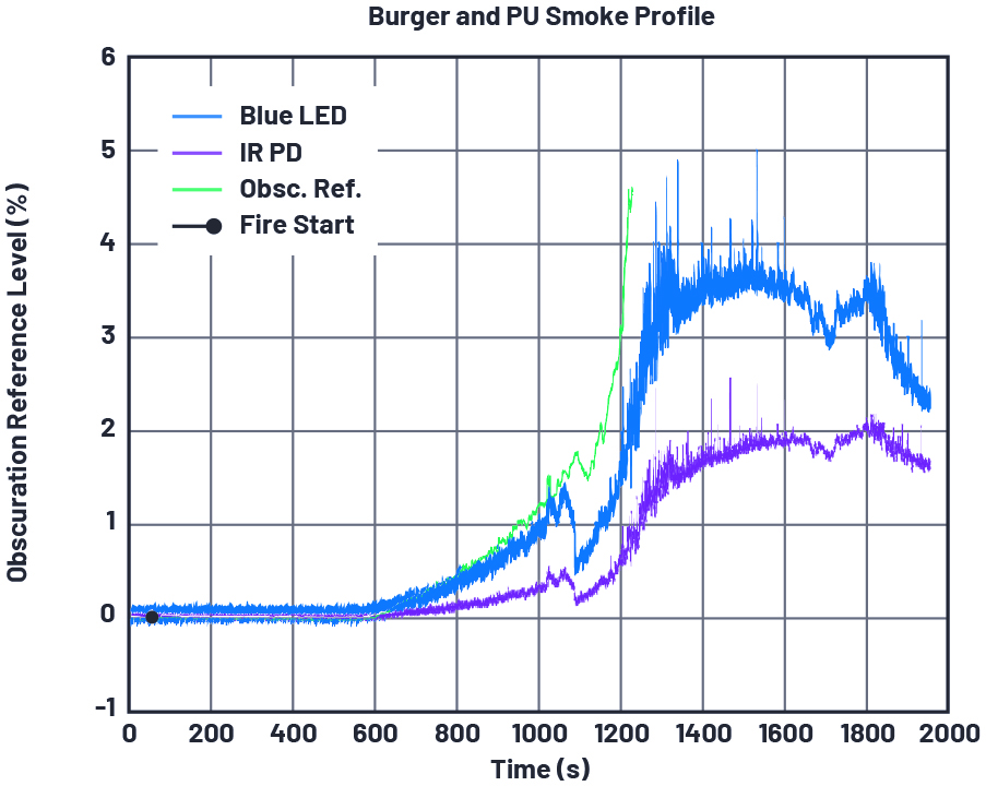
Figure 8. A burger PU smoke profile for trial 1 conducted at Intertek in February 2020 using Pod A and Device 2. Note that the obscuration reference is in units of percent/foot, whereas the sensor response is in nW/mW.
Note that the pods are always located 10' away from the fire source during this test, because this is the requirement of the nuisance aspect of the test. Because the flaming PU aspect of this test is specified at 17', the obscuration reference data is a result of splicing together data from two different beams to determine if the requirements were met. It can also be observed that while the nuisance fire has the characteristics of a slow-burning fire, the PU fire is fast-catching.
Algorithm Constraints and Design
Prior to processing the ADPD188BI sensor data for smoke detection, sensor bias needs to be computed and removed from the PTR data. Sensor bias is unique to each device and is a result of the chamber tolerances, long-term LED/PD drifts, dust or other grime buildup, etc. Moreover, its long-term behavior is affected by various factors such as ambient humidity, temperature, aging, etc. Sensor bias also varies over a long time frame and, therefore, requires tracking over a long period of time. Consequently, any smoke detector algorithm that assumes zero mean data in the absence of a fire event and employs ADPD188BI needs to periodically compute the sensor bias and subsequently remove it from the captured data.
In addition, optimizing the number of algorithm computations and, as a consequence, optimizing the system power expended on the algorithm is also an important design decision. An optional windowed average preprocessing feature provided by ADPD188BI factors into this decision. This step improves the SNR in the data at the expense of system power and is performed prior to applying any smoke detection algorithm. In our study, we were able to achieve UL 217 compliance without incorporating this step in our algorithm. Moreover, in our design, we utilized samples captured at roughly 6 second intervals, thereby greatly optimizing the system power employed for algorithm computations. Interested customers who would like to incorporate this feature may refer to this document.
As explained previously, the contrasting nature of the fast-catching and slowburning smoke profiles serves as a motivation for designing the smoke detection algorithm. ADI’s smoke detector algorithm is based on processing PTR samples as time-series data and identifying instances in time when an alarm needs to be sounded as certain key events in the time-series data are observed. ADI provides around 1500 combinations of algorithm tuning parameters that meet UL 217’s reference beam obscuration level and alarm time requirements within varying levels of success margin depending on the smoke source under consideration.
CN-0537 Smoke Detection Algorithm Performance Results
Algorithm Tuning
In this section, we discuss the performance results obtained from applying the CN-0537 smoke detection algorithm to research fire data collected at UL approved laboratories. This process also involved tuning the CN-0537 smoke detection algorithm parameters such that a large set of tuning parameter combinations are available for customers to choose from, which were found to achieve UL 217 compliance, but with varying degrees of success margin. The burger nuisance plot in Figure 9 will serve as an example smoke source to describe the performance aspects of the algorithm in general.

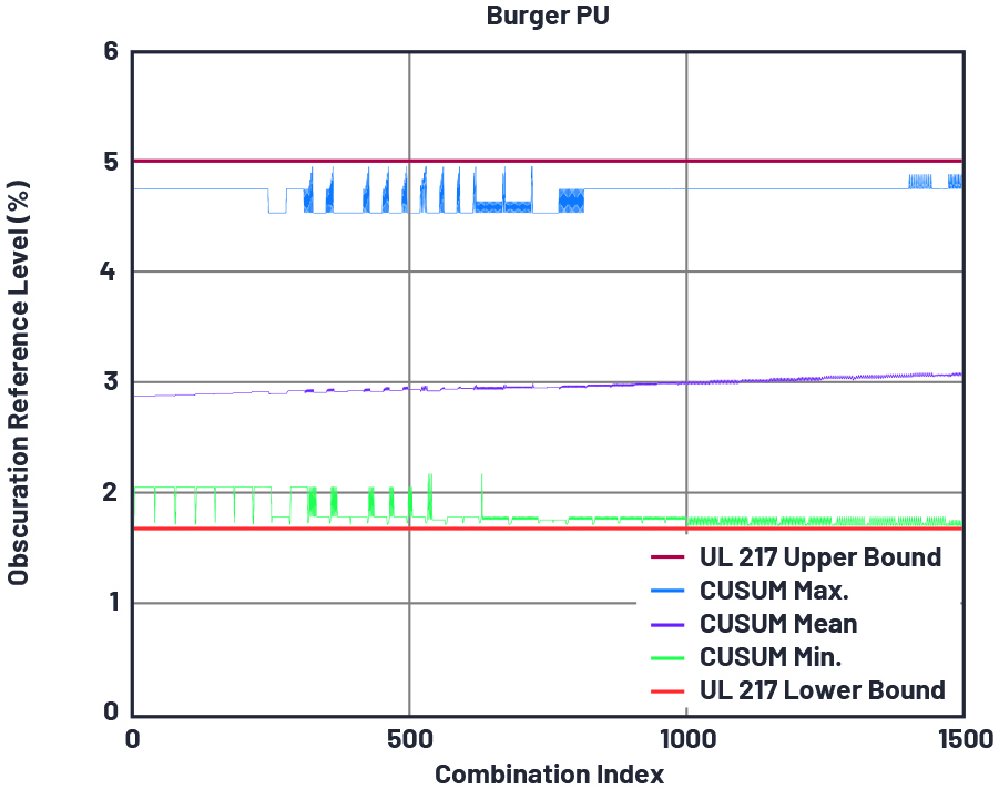
Figure 9. Reference beam obscuration level for burger PU test.
In Figure 9, the upper and the lower bounds for reference beam obscuration levels mandated by UL 217 for a burger PU test are shown. The obscuration level of the reference beam when the algorithm raises alarm is also shown. The x-axis in this figure describes the combination index of the tuning parameters.
So, for a given x-axis index, the corresponding combination of tuning parameters has been applied to all the data files and the obtained results have been categorized. As shown in Figure 9, while all combinations of tuning parameters render the algorithm compliant with UL 217, the margin between the alarm time obscuration level and the target obscuration level can be very close. Furthermore, it can be observed that while a combination of tuning parameters might provide sufficient margin for some smoke sources, they might result in close calls for others. Hence, the selection of tuning parameters has to be made by accounting for all smoke sources.
As an example, we see from Figure 9 that UL 217 stipulates that the algorithm alarms below the reference beam obscuration level of 5% and above 1.5%. For a given tuning parameter combination—say, index 500 and among all the smoldering burger and PU tests—the largest obscuration level among all the burger and PU fire datasets at which the algorithm raised an alarm was around 4.7%; that is, within the stipulated level. Similarly, the smallest obscuration level among all the burger nuisance fire datasets at which the alarm was raised was around 2%. This variation is primarily a result of the variations in conducting the test either by the technician or due to the inherent randomness in the smoke profile itself from one test to another.
UL 217 Test Results
Following algorithm design and tuning using a research fire dataset, the algorithm was tested for UL 217 compliance. A summary of Intertek’s test results using the CN-0537 smoke detection algorithm can be seen in Table 2, and the detailed report is available here. Note that, although EVAL-CN0537-ALGO is tested and verified to pass the UL 217 8th edition fire tests, it is primarily intended to facilitate customers to focus on the larger task of creating their end product. In other words, even when using the algorithm ADI has developed, customers are still required to have their end product certified in its entirety against the UL 217 standard. Note also that only the smoke detector aspects of UL 217 have been tested and verified and not the other portions of UL 217, such as those that focus on the mechanical aspects, battery life, etc.
| Test | UL 217 8th Edition Section | Result |
| Directionality | 43 | Pass |
| Sensitivity | 42 | Pass |
| UL: paper fire | 51.2 | Pass |
| UL: wood fire | 51.3 | Pass |
| UL: flaming PU foam test | 51.4 | Pass |
| UL: smoldering smoke test | 52 | Pass |
| UL: smoldering PU foam test | 53 | Pass |
| UL: cooking nuisance smoke test | 54 | Pass |
| UL: go/no go flaming PU foam test | 54 | Pass |
| Velocity sensitivity | 44 | Pass |
| Variable ambient (0°C and 49°C) | 62 | Pass |
| Humidity | 63 | Pass |
ADI Solution Options
To address the needs of different customers, a number of solution offerings are available and summarized in Figure 10. The hardware is Arduino form factor compatible and is designed to accelerate prototyping and the evaluation of the embedded smoke detection algorithm. The hardware is comprised of the EVALCN0537-ARDZ reference design, which is described in the CN-0537 circuit note and the supporting EVAL-ADICUP3029 microcontroller board. The data (EVAL-CNO537- DATA) package provides an extensive smoke dataset taken at UL 217 certified facilities for those who wish to develop their own algorithm and the CN-0537 source code excluding the detection algorithm. The algorithm (EVAL-CN0537-ALGO) package includes everything in the data package and a UL tested and verified smoke detection algorithm with associated algorithm project files.

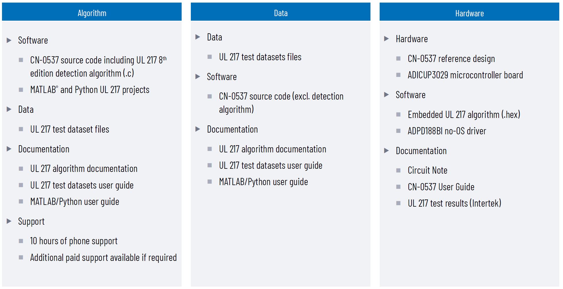
Figure 10. CN-0537 reference design offerings.
关于作者
最新视频 21


