概览
设计资源
描述
Industry 4.01 marks the fourth industrial revolution, characterized by distributed, intelligent control systems. Breaking from a past with large, centralized programmable-logic controllers, Industry 4.0 allows for highly configurable, highly modular factories, which accept an ever increasing number of sensor inputs, while operating at a higher output than ever before. The ultra-small PLC, or MicroPLC, lies at the heart of the Industry 4.0 factory, providing high performance with ultra-low power consumption, in an ultra-small package. MAXREFDES63 is Analog’s Micro PLC octal-channel, digital output card.
The MAXREFDES63 reference design (Figure 1) features eight-channel digital outputs with isolated power and data. The design integrates a 600VRMS data isolation (MAX14850); a STM32F1 microcontroller; a FTDI USB-UART bridge; a high-efficiency DC-DC converter (MAX17515); and isolated/regulated +22V, and +5V power rails (MAX17498C). The entire system typically operates at less than 400mW and fits into a space roughly the size of a credit card.
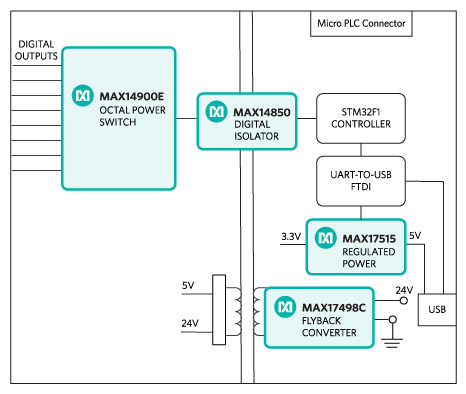
Figure 1. The MAXREFDES63# reference design block diagram.
优势和特点
- Isolated power and data
- Micro PLC form factor
- Device drivers
- Example C source code
详情
Industry 4.01 marks the fourth industrial revolution, characterized by distributed, intelligent control systems. Breaking from a past with large, centralized programmable-logic controllers, Industry 4.0 allows for highly configurable, highly modular factories, which accept an ever increasing number of sensor inputs, while operating at a higher output than ever before. The ultra-small PLC, or MicroPLC, lies at the heart of the Industry 4.0 factory, providing high performance with ultra-low power consumption, in an ultra-small package. MAXREFDES63 is Analog’s Micro PLC octal-channel, digital output card.
The MAXREFDES63 reference design (Figure 1) features eight-channel digital outputs with isolated power and data. The design integrates a 600VRMS data isolation (MAX14850); a STM32F1 microcontroller; a FTDI USB-UART bridge; a high-efficiency DC-DC converter (MAX17515); and isolated/regulated +22V, and +5V power rails (MAX17498C). The entire system typically operates at less than 400mW and fits into a space roughly the size of a credit card.
Figure 1. The MAXREFDES63 reference design block diagram
The power requirement is shown in Table 1.
Power Type | Input Voltage (V) | Input Current (mA, typ) |
On-board isolate power | 24 | 15 (All LEDs on) + Load Current |
Note: STM32 and FTDI are powered by USB separately.
The MAX14900 (U400) is an octal power switch with per-channel configuration feature.
The ultra-efficient MAX17498C (U102) generates the isolated +22V, and +5V rails from a 24V supply. The MAX14850 (U301) digital data isolators provide data isolation. The combined power and data isolation achieved is 600VRMS.
The MAX17515 (U101) step-down DC-DC converter converts the +5V supply from the USB to +3.3V and powers the STM32 (U1) microcontroller and FTDI (U201) USB-UART bridge.
Detailed Description of Firmware
The MAXREFDES63 uses the on-board STM32F1 microcontroller to communicate with the octal power switch. The user enters configuration data through a terminal program and the digital outputs will be updated. The simple process flow is shown in Figure 2. The firmware is written in C using the Keil µVision5 tool.
Figure 2. The MAXREFDES63 firmware flowchart
The complete source code is provided to speed up customer development. Code documentation can be found in the corresponding firmware platform files.
Required equipment:
- Windows® PC with a USB port
- MAXREFDES63 board
- 24V power supply
Procedure
The complete source code is provided to speed up customer development. Code documentation can be found in the corresponding firmware platform files.
- Turn off or keep off the 24V power supply.
- The MAXREFDES63 utilizes the FTDI USB-UART bridge IC. If Windows cannot automatically install the driver for the FTDI USB-UART bridge IC, the driver is available for download from www.ftdichip.com/Drivers/D2XX.htm.
- Connect the negative terminal of the 24V power supply to the PGND connector on the MAXREFDES63 board. Connect the positive terminal of the 24V power supply to the +24V connector on the MAXREFDES63 board.
- Turn on the 24V power supply.
- Connect the USB cable from the PC to the MAXREFDES63 board.
- Open Hyperterminal or similar Terminal program on the PC. Find the appropriate COM port, usually a higher number port, such as COM4, or COM6, and configure the connection for 921600, n, 8, 1, none (flow control).
- The MAXREFDES63 software will display a menu (Figure 3)
- Press any key in the terminal program to start the output configuration.
- Enter the Configuration Byte in hex format.
- Enter the desired output data in hex format.
- Verify the output status by observing the 8 green LEDs under connectors J400 and J401 on the board. These LEDs are connected to the digital outputs of the card.
Figure 3. Terminal program main menu
Figure 4 and Figure 5 shows the status of the LEDs with the output configuration byte set to 0xFF and the output data byte set to 0xAA.
Figure 4. Test setup.
Figure 5. Test outputs
Reference
The new generation of manufacturing production is called Industry 4.0 in Germany and Smart Manufacturing System elsewhere. See, Securing the future of German manufacturing industry, Recommendations for implementing the strategic initiative INDUSTRIE 4.0, Final report of the Industrie 4.0 Working Group, Industry 4.0 Working Group, Acatech National Academy of Science and Engineering, April 2013, https://www.acatech.de/wp-content/uploads/2018/03/Final_report__Industrie_4.0_accessible.pdf. Henceforth cited as Industrie 4.0. Although the Industrie 4.0 report is focused on Germany, the implications of the German research and findings are recognized for industry in other countries. See also Ferber, Stefan, “Industry 4.0 – Germany takes the first steps toward the next industrial revolution,” Bosch Software Group, Blogging the Internet of Things, October 16, 2013, http://blog.bosch-si.com/industry-4-0-germany-takes-first-steps-toward-the-next-industrial-revolution/.
There are many sources for Smart Manufacturing Leadership. An interesting summary report of issues and topics can be found at the Smart Manufacturing Leadership Coalition Committee Working Meeting, Minneapolis, MN, U.S., Thursday, October 20, 2011, https://smart-process-manufacturing.ucla.edu/workshops/2011-workshop/presentations/SMLC%2010-20-11v3.pdf. Also see, Implementing 21st Century Smart Manufacturing, Workshop Summary Report, Smart Manufacturing Leadership Coalition, June 24, 2011, https://smart-process-manufacturing.ucla.edu/about/news/Smart%20Manufacturing%206_24_11.pdf. A simple web search on the topic will reveal considerably more references.
文件和资源
-
MAXREFDES63 Design Files2021/2/17ZIP5 M
支持与培训
搜索我们的知识库,获取技术问题答案。我们专门的应用工程师团队也会随时为您解答技术问题。