The MAXREFDES173# is a complete, high-accuracy, IO-Link®, local temperature sensor reference design that provides excellent temperature accuracy from -40°C to +85°C. Built in an industrial form factor, the design makes use of the ADI MAX31875 digital temperature sensor with an I2C interface.
The MAX31875 operates over the −50°C to +150°C temperature range and measures temperatures from −40°C to +145°C with an accuracy of ±1.75°C or better. The temperature sensor performs more accurate temperature conversions from 0°C to +70°C (±1.0°C).
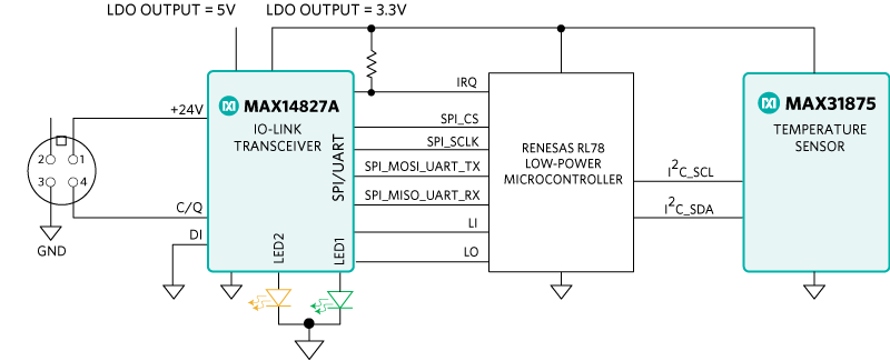
A Renesas RL78 (R5F10E8EALA) microcontroller interfaces between the MAX31875 temperature sensor and the MAX14827A IO-Link device transceiver. The RL78 microcontroller operates from −40°C to +85°C. The 3.3V and 5V rails are generated by two integrated LDO regulators within the MAX14827A, which reduces the number of required external components and the required circuit footprint. Both the MAX31875 and the MAX14827A are low-power devices, which allow this reference design to consume minimal power with low thermal dissipation. Additionally, both ADI products are in wafer-level packages (WLPs), giving the MAXREFDES173# a tiny overall footprint.
This sensor utilizes the IQ2 Development™ IO-Link device stack to communicate with any IO-Link version 1.1-compliant master. The board contains a male M12 connector for connection to a compliant IO-Link master using a standard M12 cable. Connect the MAXREFDES173# to any IO-link master for easy evaluation (for example, the iqLink® USB IO-Link Master with the associated software).
Design files, firmware, and software are available on the Design Resources tab. The board is also available for purchase.
优势和特点
IEC 61131-9 Compliant
IQ2 Development IO-Link Stack
IO-Link Version 1.1 Compliant
Measures Temperature from −40°C to +85°°C with ±1.75°C Accuracy
Advanced factory automation solutions (i.e., Industry 4.0), require an increasing number of smart sensors, which are typically controlled using IO-Link point-to-point serial communication between the sensor and controller (master). As a leading provider of IO-Link sensor transceiver and master transceiver ICs, Maxim® also provides complete reference design solutions to help customers improve their time to market. These proven designs cover all the hardware and software requirements needed for compliance with the IO-Link standard. The complete MAXREFDES173# reference design, including all of the ICs and external protection devices such as varistors, is provided on a 7.5mm wide printed circuit board (PCB).
Maxim Integrated collaborated with IQ2 Development to design the MAXREFDES173# as a temperature sensor reference design that is compliant with the IO-Link version 1.1/1.0 standard. The MAXREFDES173# design consists of an industry-standard MAX14827A IO-Link device transceiver, a Renesas RL78 microcontroller that uses the IQ2 Development IO-Link device stack, and a MAX31875 local temperature sensor.
The MAXREFDES173# IO-Link local temperature sensor consumes minimal power, space, and cost, making it a complete solution for many industrial control and automation local temperature-sensing applications.
The MAX14827A IO-Link device transceiver is compliant with the IO-Link version 1.1/1.0 physical layer specification. It integrates the high-voltage functions commonly found in industrial sensors, including drivers and regulators, all in a tiny 2.5mm x 2.5mm WLP. The MAX14827A features two ultra-low power drivers with active reverse-polarity protection. Operation is specified for normal 24V supply voltages up to 60V. Transient protection is simplified due to high voltage tolerance (a 65V absolute maximum rating), allowing the use of varistors or micro TVS diodes.
The device features a flexible control interface. An SPI interface is available with extensive diagnostics, and a 3-wire UART interface is provided for IO-Link operation. The MAXREFDES173# takes advantage of the multiplexed UART/SPI option, which allows using one serial microcontroller interface for shared SPI and UART interfaces. The MAX14827A includes integrated 3.3V and 5V linear regulators, which provide the low-noise supply rails for the other components on the board.
The MAX31875 is a ±1°C-accurate local temperature sensor with an I2C/SMBus interface. The combination of a tiny package and excellent temperature measurement accuracy makes this product ideal for a variety of equipment. The MAX31875 measures temperature and converts the data into digital form, and then the I2C-compatible, 2-wire serial interface allows access to conversion results. Standard I2C commands allow reading the data and configuring other operating characteristics. The MAX31875 is available in a 4-bump WLP and measures temperature over the −40°C to +145°C temperature range.
For protection, the MAXREFDES173# uses a TVS diode array at the IO-Link interface. The uClamp3603T µClamp®TVS diodes have a working voltage of 36V and a minimum breakdown voltage of 37V. With these TVS diodes, this reference design meets both IEC 61000-4-2 for electrostatic discharge (ESD) up to 4kV (i.e., contact and air gap) and IEC 61000-4-4 for electrical fast transient (EFT) up to 4kV. It is also designed to survive surge pulses (2A at t = 1.2/50μs) up to 1.2kV. The MAX14827A absolute maximum (abs max) voltage rating of 65V on the IO-Link pins allows the use of these TVS diodes in an ultra-small package where other transceiver ICs with lower abs max ratings require much larger-sized TVS diodes.
The MAXREFDES173# uses an industry-standard M12 connector, which allows a 4-wire cable to be used.
The MAXREFDES173# consumes less than 6mA (typ). A green LED “alive signal” pulses instead of remaining constantly on to reduce power consumption. A yellow LED indicates a FAULT condition if illuminated.
Detailed Description of Software
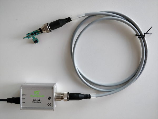
As seen in Figure 2, the MAXREFDES173# has been verified using the iqLink IO-Link master (featuring the MAX14819 IO-Link master transceiver) and the IODD interpreter tool iqPDCT® from IQ2 Development. Download the IODD file (*.xml) located in the Design Resources tab and go to the Quick Start Guide section for step-by-step instructions on how to use the software.
Figure 2. MAXREFDES173# was verified with the iqLink Master from IQ2 Development.
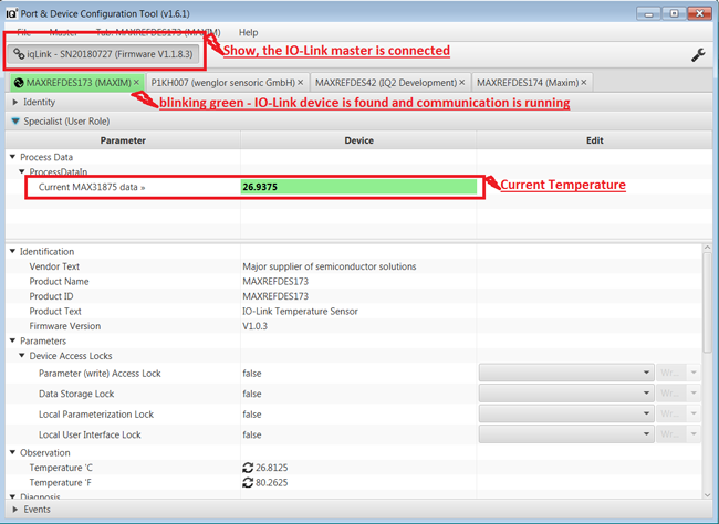
Figure 3 shows a screenshot of the IQ2 Development iqPDCT IO-Link Device Tool communicating with the master and sensor.
Figure 3. The iqPDCT IO-Link Device Tool with the MAXREFDES173#.
Detailed Description of Firmware
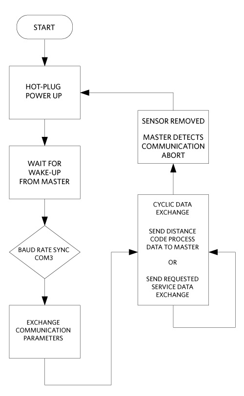
The MAXREFDES173# ships preprogrammed as a working IO-Link temperature sensor ready to connect to an IO-Link master. The firmware targets the RL78 microcontroller and follows the simple flowchart shown in Figure 4.
Figure 4. MAXREFDES173# firmware flowchart.
The firmware utilizes the IQ2 Development IO-Link device stack. After hot plug-in, the MAXREFDES173# waits for a wake-up signal from the IO-Link master. When the wake-up signal is received, the MAXREFDES173# synchronizes to the IO-Link master using the 230.4kbps (COM3) baud rate, and communication parameters are exchanged. The IO-Link Master then starts a cyclic data exchange by requesting the sensor process data. If the sensor is removed, the IO-Link master detects a missing sensor.
The IQ2 Development iqPDCT IO-Link Device Tool software is Windows®-compatible and features IODD file import capability, connects to a PC through USB, and is available to download from the IQ2 Development website when an IQ2 Development master has been purchased. The IQ2 Development IO-Link Device Tool software is shown in Figure 3, and a complete guide is also downloadable from IQ2 Development.
Source code for the MAXREFDES173# is not available. The IQ2 Development IO-Link device stack ships preprogrammed in the MAXREFDES173# hardware with a perpetual license. The IQ2 Development contact information is as follows:
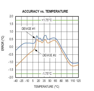
To test the sensor accuracy, the MAXREFDES173# was placed in a temperature chamber. The temperature measured by the device was compared to the temperature measured by a precision thermocouple. Two MAXREFDES173# devices were tested.
Figure 5 shows the accuracy versus temperature measurements over the −40°C to +125°C range. The maximum operating temperature of the RL78 microcontroller is +85°C, but for this case we tested to +125°C. The accuracy of the MAXREFDES173# over the entire temperature range is well within the target specification of ±1.75°C from the MAX31875 data sheet.
Figure 5. Accuracy versus temperature for the MAXREFDES173#.
EMC Requirements Defined by IO-Link Interface and System Specification Version 1.1.2
IO-Link is a single-drop communication interface (SDCI), and Annex G of the IO-Link Interface and System Specification provides the recommended EMC test conditions for the SDCI interface of a master or device product. The EMC test levels are shown in Table 1 and are taken from Table G.2 of the IO-Link Interface and System Specification.
Table 1. EMC test levels specified by IO-Link Interface and System Specification Version 1.1.2
80MHz to 1000MHz 10V/m 1400MHz to 2000MHz 3V/m 2000MHz to 2700MHz 1V/m
A
See G.1.4. a) and G.1.4, b)
Fast transients (Burst) IEC 61000-4-4
±1kV
A
5kHz only. The number of M-sequencers in Table G.1 shall be increased by a factor of 20 due to the burst/cycle ratio 15ms/300ms. See G.1.4,c)
±2kV
B
Surge IEC 61000-4-5
Not required for an SDCI link (SDCI link is limited to 20 m)
—
ZRadio-frequency common mode IEC 61000-4-6
0.15MHz to 80MHz 10V EMF
A
See G.1.4. b) and G.1.4, d)
Voltage dips and interruptions IEC 61000-4-11
Not required for an SDCI link
—
The IO-Link EMC requirements define two performance criteria. Criterion A requires no more than six detected M-sequence errors and no interruption of communication. Criterion B does not allow a change in the stored data or of the actual operating state (e.g., permanent loss of communication).
The general rules for the test configuration of a device (such as the MAXREFDES173#) are as follows:
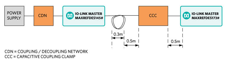
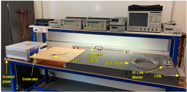
SDCI cable shall be unshielded and 20m long, coiled, and placed 10cm (4”) above the ground plane
The devices shall be placed 10cm (4”) above the ground plane
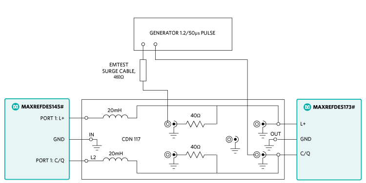
For the EFT test setup according to IEC 61000-4-4, see Figure 9
The MAXREFDES173# was tested in a Maxim lab for the common industrial compliance standards, and the test methodology and results are presented. Although the IO-Link Interface and System Specification does not require surge testing, Maxim did this test in addition to the ESD and EFT tests.
The MAXREFDES173# was tested to withstand up to ±1.2kV of 1.2/50µs IEC 61000-4-5 surge with a total source impedance of 500Ω. Surge testing was performed using the MAXREFDES145# IO-Link master, and 10 surge pulses were applied for each test as shown in Table 2. The MAXREFDES173# was not damaged by the tests.
The performed surge tests are defined as follows:
L+ to GND: Communicating with the master, the module continued to execute code and transfer data, and the MAX14827A registers were not corrupted.
CQ to GND: Communicating with the master, the module continued to execute code and transfer data, and the MAX14827A registers were not corrupted.
L+ to CQ: Communicating with the master, the module continued to execute code and transfer data, and the MAX14827A registers were not corrupted.
Using a 20m IO-Link cable with standard M12 connectors, the MAXREFDES173# was tested to withstand electrical fast transient (EFT)/bursts up to ±4kV according to IEC 61000-4-4. EFT testing was performed using the MAXREFDES145# IO-Link master, and EFT pulses were applied for one minute for each test, as shown in Table 3. Repetition rates of 5kHz and 100kHz were tested, along with burst lengths of 15ms and 0.75ms. The MAXREFDES173# was not damaged by the test, and the MAX14827A registers were not corrupted.
Table 3. EFT/Burst Test Results
Test Condition
5kHz/15ms
100kHz/0.75ms
+4kV
Pass
Pass
−4kV
Pass
Pass
Figure 8. Test setup for fast transients (device).
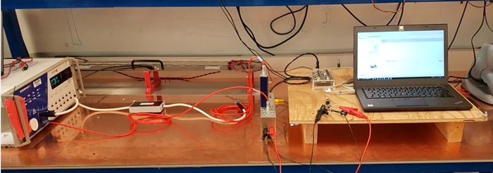
Figure 9. EFT/burst testing.
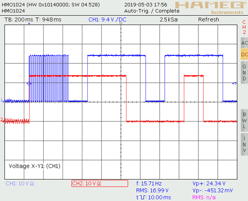
Due to test equipment limitations, we were unable to count M-sequence errors. To validate if the MCU on the MAXREFDES173# was susceptible to EFT, it was programmed to generate square-wave outputs to toggle the C/Q and DO pins. On the square wave, disturbances that imply communication errors were not detected (i.e., the high and low levels were always within their range).
It was clear that the MAX14827A did not go through a reset because the reset settings of the MAX14827A could have disabled the CQ output driver. Additionally, the microcontroller firmware was set up to toggle C/Q very fast every time the microcontroller was reset (Figure 10). This clearly indicates if a reset occurred on the microcontroller, which also causes the MAX14827A registers to be re-initialized by the microcontroller. The pass/fail criteria were that the high/low levels were not disturbed and no fast-toggling was observed.
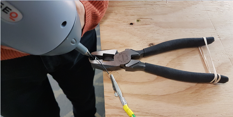
The MAXREFDES173# was tested to withstand electrostatic discharge (ESD) for contact and air-gap discharge up to ±4kV according to IEC 61000-4-2. ESD testing was performed on the MAXREFDES173# M12 connector pins, after the test operation was verified using the MAXREFDES145# IO-Link master to transfer data, as shown in Table 4. The MAXREFDES173# was not damaged by any ESD tests and continued to operate normally.
Table 4. ESD Test Results
Test Condition
L+ to GND
CQ to GND
+4kV Contact Discharge
Pass
Pass
−4kV Contact Discharge
Pass
Pass
+4kV Airgap Discharge
Pass
Pass
−4kV Airgap Discharge
Pass
Pass
Note that the IO-Link Interface and System Specification Version 1.1.2 requires ESD testing with a 20m cable attached, and the ESD strike is applied to the sensor casing. Because this reference design is only a PCB with no metallic casing, the ESD strikes were applied to the male M12 connector pins. Maxim expects this design to meet the levels specified in Table G.2 when testing with a casing and cable (Table 1).
Figure 11. ESD testing.
Maxim Reference Design Use Restrictions and Warnings
The MAXREFDES173# is designed and tested to meet IO-Link operation and harsh industrial environments covered by IEC 61000-4-x standards for transient immunity. This board and associated software are designed to be used to evaluate the performance of the MAX14827A but are not intended to be deployed as-is into an end-product in a factory automation system.
The MAXREFDES173# is not for use in functional safety and/or safety critical systems.
To test the MAXREFDES173# sensor, connect it to a port of an IO-Link master. In the following example, an iqLink IO-Link master is used, but any IO-Link compliant master and associated IO-Link device GUI should work.
Required Equipment
Supplied by Maxim:
MAXREFDES173#
Note: Download files from the Design Resources tab.
User Supplied:
IO-Link master (i.e., the iqLink) with an AC-to-DC 24V power adapter
iqPDCT IO-Link Device Tool Software
One IO-Link cable
Windows 7, Windows 8, or Windows 10 PC with a USB port
Procedure
Master Setup Procedure
Connect the MAXREFDES173# sensor to the IO-Link master with an IO-Link M12 cable.
Connect the IO-Link master to the PC with a USB cable.
Download and install the latest iqPDCT software from the IQ2 Development website (http://www.iq2-development.de).
Download the IODD file for the MAXREFDES173# from the Design Resources tab or from the IQ2 Development website (http://www.iq2-development.de).
The MAXREFDES173# comes programmed with firmware.
Sensor Testing Procedure
Connect the female end of the IO-Link cable to the MAXREFDES173#.
Connect the male end of the IO-Link cable to one of the ports on the IO-Link master.
Open the iqPDCT software.
Import the IODD file for the MAXREFDES173#.
Press the Connect button.
If communication is established correctly, the iqPDCT software shows the IO-Link master connection, the device tab blinks green, and the process data shows the current temperature, as shown in Figure 12.
Apply heating or cooling to the sensor to observe continuous updating of the temperature in degrees Celsius.