概览
设计资源
描述
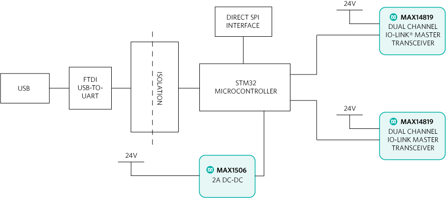
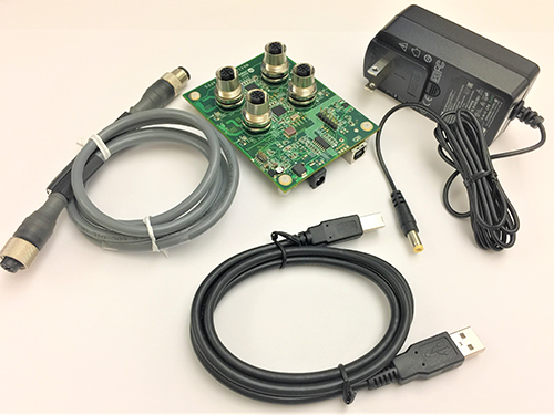
The MAXREFDES165# is a fully IO-Link®-compliant, 4-port IO-Link master reference design. This design uses the TMG TE IO-Link master stack and is both an IO-Link master reference design and a development and test system for IO-Link sensors/actuators. Four IO-Link ports allow for simultaneous testing of up to four different sensors (or actuators). The reference design has four robust female M12 connectors—the most common connector used for IO-Link—and ships with an IO-Link cable for connecting quickly to IO-Link compatible sensors and actuators. An AC-to-DC (24VDC/1A) power supply is capable of providing at least 250mA to each port simultaneously, and more when fewer ports are used. A USB 2.0 Type B connector allows for quick connectivity to a Windows® PC.优势和特点
Features:
- Fully IO-Link Version 1.1 compliant
- TMG TE IO-Link master stack
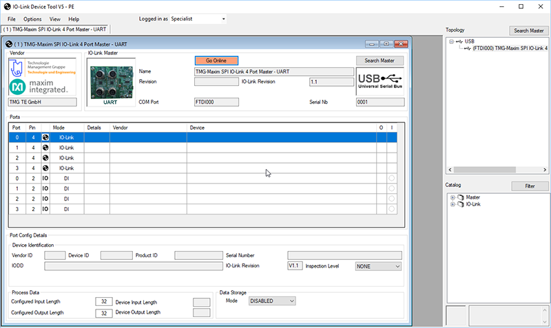
- Easy-to-Use IO-Link Device Tool V5 from TMG
- 4 IO-Link master ports
- Ships with all required cables
- Field-update programmable
Competitive Advantages
- Simultaneous four-port operation
- Easy-to-use GUI
- IODD import
详情
IO-Link is the first open, field-bus agnostic, low-cost, point-to-point serial communication protocol for communicating with sensors and actuators. Adopted as an international standard (IEC 61131-9), IO-Link standardizes interoperability of industrial equipment from all over the world. IO-Link can function directly from the PLC or can be converted from all standard field busses through a gateway, quickly making it the de facto standard for universal communication with smart sensors and actuators.
IO-Link is a single-drop digital communication interface (SDCI), which means it supports only one sensor or actuator per port. The three-wire protocol is also backward compatible with binary sensors and actuators that use standard inputs and outputs. IO-Link device descriptor (IODD) files completely define the device and eliminate manual parameterization.
The MAXREFDES165# design utilizes two MAX14819 dual-channel Maxim Integrated IO-Link master transceivers, an on-board digital isolator, the efficient industrial MAX15062AATA+ step-down converter, a FTDI USB-to-SPI interface, and a STMicroelectronics® 32-bit Arm® Cortex®-M4 microcontroller (STM32F4) utilizing TMG TE’s IO-Link Device Tool software and TMG TE’s IO-Link master stack. Figure 1 is the system block diagram of the MAXREFDES165# design.
The MAXREFDES165# Reference Design Block Diagram.
Detailed Description of Hardware
The MAXREFDES165# IO-Link master comprises four main blocks:
- Two dual-channel MAX14819 IO-Link master transceivers
- A MAX14931 digital isolator for the SPI interface
- A microcontroller
- A USB connection (shown in Figure 1)
The MAX14819 IO-Link master transceivers are IO-Link version 1.1.2 physical-layer compliant. These transceivers feature integrated 5V linear regulators, configurable C/Q outputs (push-pull, high-side, or low-side) with configurable output drive capability, auxiliary digital inputs, and reverse-polarity/short-circuit protection.
An STM32F4 Arm Cortex-M4 microcontroller in a 10mm x 10mm, 64-pin LQFP package provides system control. A USB port is implemented using the FTDI FT2232 USB-to-SPI transceiver and driver. An on-board MAX15062A high-voltage, synchronous step-down converter provides power to the STM32F4 microcontroller from the 24V supply.
A digital isolator, the four-channel MAX14931F protects the USB interface from high-voltage and large ground differentials that can occur when the MAX14819 master transceivers are connected to IO-Link peripherals. All communication between the USB port/PC and the SMT32F4 microcontroller passes through this isolator.
A stand-alone SPI header (J3) is available on the MAXREFDES165# to allow the user to bypass the USB interface and communicate directly with the STM32F4 using an external SPI master. J3 is connected to the isolated side of the board and all digital communication from the external master to the STM32F4 goes through the isolators. An external 3.3V logic supply to power the isolators is required when using J3.
High-level protection transient voltage suppressor (TVS) diodes at each of the four IO-Link interface ports and at the power supply inputs provide surge and reverse-polarity protection for each master transceiver on the MAXREFDES165#.
Additionally, power and status LEDs (for each channel) provide quick visual confirmation that the board is working and communicating.
Figure 2 shows the box contents for the MAXREFDES165# reference design.
Figure 2. MAXREFDES165# box contents.
The MAXREFDES165# box contents include the following:
MAXREFDES165# four-port IO-Link master
- TMG IO-Link Master Stack
- AC-to-DC 24V/1A (min) output power converter
- One IO-Link cable
- USB 2.0 Type B cable
Necessary downloadable software includes:
- TMG IO-Link Device Tool V5 Software
- FTDI® driver
The MAXREFDES165# typically consumes 30mA from the 24V supply at 25°C with no sensors attached.
Detailed Description of Software
TMG IO-Link Device Tool Windows-compatible software features IODD file import capability and connects to a PC through USB. The TMG IO-Link Device Tool software is shown in Figure 4, and a complete step-by-step Quick Start guide is also available in the design file package.
Note: The MAX14819 can be configured to operate with a UART interface (within the microcontroller) or by using the integrated framers on the IC. The default stack that ships with the MAXREFDES165# is the UART version. If you require the Framer version please contact the factory.
Figure 4. MAXREFDES165# TMG IO-Link Device Tool
The TMG TE IO-Link master stack ships preprogrammed inside the MAXREFDES165# hardware with a perpetual license. TMG contact information is as follows:
TMG Technologie Management Gruppe
Technologie und Engineering GmbH
Zur Gießerei 10
76227 Karlsruhe
Phone +49 721 82 806 0
Fax +49 721 82 806 10
Quick Start Guide
Required Equipment:
Supplied by Analog:
- MAXREFDES165# (box contents)
- MAXREFDES165# four-port IO-Link master
- TMG IO-Link Device Tool software (Note 1)
- AC-to-DC 24V/1A output power converter
- One IO-Link cable
- USB 2.0 Type B cable
User supplied:
- Windows 7, Windows 8, or Windows 10 PC with a USB port
- IO-Link sensor or IO-Link actuator (Note 2)
Note 1: Download design files.<="" a="">
Note 2: Analog Devices offers multiple IO-Link sensor reference designs for immediate operation with the IO-Link master. Refer to MAXREFDES23, MAXREFDES27, MAXREFDES36, and MAXREFDES42.
Download, read, and carefully follow each step in the MAXREFDES165 Quick Start Guide
IO-Link Compliance Report
The MAXREFDES165# is a fully compliant IO-Link version 1.1 master, according to the following test report. It was tested with golden device GD000010.
IO-Link is a registered trademark of Profibus User Organization (PNO).
Arm is a registered trademark and registered service mark of Arm Limited.
Cortex is a registered trademark of Arm Limited.
Windows is a registered trademark and registered service mark of Microsoft Corp.
FTDI is a registered trademark and service mark of Future Technology Devices International Limited.
STMicroelectronics is a registered trademark of STMicroelectronics, Inc.
文件和资源
-
MAXREFDES165 Design and Software Files2021/7/14ZIP17 M
支持与培训
搜索我们的知识库,获取技术问题答案。我们专门的应用工程师团队也会随时为您解答技术问题。