DS1375 Power Line to 60Hz Clock
Abstract
The DS1375 2-wire digital real-time clock (RTC) is a low-power, clock/calendar that can operate from a digital clock input at one of four frequencies: 32.768kHz, 8.192kHz, 60Hz, or 50Hz. This application note shows how to derive the 60Hz clock from the power line and use it as a clock for the DS1375.
Power Line Frequency
The 60Hz power line frequency is very carefully monitored. Throughout the day this frequency varies and tends to slow down during times of heavy use. Toward the end of the day the power company speeds up/slows down the frequency as needed so the total cycles in a given day is 5,184,000. In places that AC power is always available, a clock that uses a power line frequency of 60Hz will always be accurate over the long term.
The Circuits
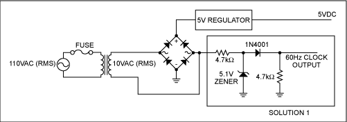
The circuit in Solution 1 uses a transformer to step the 110 VAC power line to a safer 8 VAC (RMS). This circuit provides an inexpensive solution to extract the 60Hz clock from the power line. The 5.1V zener limits the AC to just the positive half of the cycle and suppresses anything more than 5.1V. The 1N4001 diode is then used to reference this to ground.
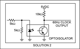
If isolation is a concern, an optoisolator can be used (Solution 2) for additional cost.
Configuring the DS1375 for 60Hz Clock Input
To use an external 60Hz input, the DS1375 must be configured to accept this as a clock. This is done through the control register at address 0Eh, shown in Table 1. When ECLK is set to logic 1, the CLK input pin is enabled to clock the internal divider chain and advance the timekeeping registers. CLKSEL1 and CLKSEL0 determine how the CLK input pin is divided down to get the 1Hz reference clock for the timekeeping registers: Setting CLKSEL1 to 1 and CLKSEL0 to 0 configures the divider chain to accept a 60Hz clock.
Table 1. Control register at address 0Eh| Bit 7 |
Bit 6 | Bit 5 | Bit 4 | Bit 3 | Bit 2 | Bit 1 | Bit 0 |
| ECLK |
CLKSEL1 |
CLKSEL0 |
RS2 |
RS1 |
INTCN |
A2IE |
A1IE |

Figure 1. Circuit to extract the 60Hz clock from the power line.

Figure 2. Optoisolator solution for extracting a 60Hz clock.