AN-840: Code Update via I2C®
Introduction
The ADuC702x family features an in-circuit programming capability. For standard models, this is based on the UART interface. On the following I models, the in-circuit programming capability is based on the I2C interface: ADuC7019BCPZ62I, ADuC7020BCPZ62I, ADuC7021BCPZ62I, and ADuC7026BSTZ62I.
For both the standard and I models, a hardware switch is required to enter download mode at reset (see the AN-724 and AN-806 application notes).
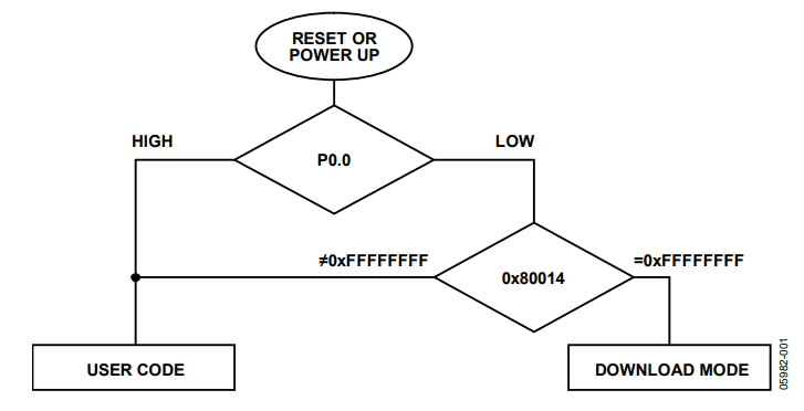
On the I models, a software switch is also necessary to enter download mode, as shown in Figure 1.
Some applications cannot allow for a hardware switch on P0.0, but still require software update capabilities via I2C. This application note only describes how to update the software with P0.0 permanently grounded.

Dangers
P0.0 grounded means that users should only rely on the contents of Address 0x80014, as follows:
- If Address 0x80014 is cleared (=0xFFFFFFFF), the part is in download mode after reset. JTAG cannot be used because the kernel is protected against JTAG access. The loader expects commands on the I2C0 bus (P1.0 and P1.1). User code does not run unless the loader receives a run command (see AN-806 for more information).
- If Address 0x80014 is not cleared, the part is in user mode. It cannot enter download mode unless Address 0x80014 is erased and the part is power cycled or reset.
Testing The I2C Loader and Debugging Code on I Models
To download code to the ADuC702x via I2C, Address 0x80014 must be erased. To ensure code can always be updated via I2C on the part, use one of these methods:
- Ensure Address 0x80014 always contains 0xFFFFFFFF. To do so, modify the start-up code and use I2CWSD to download the code via I2C.
- Use JTAG to erase the Flash/EE memory.
- Define a protocol build in the user code to erase Page 0 of the Flash/EE memory.
The two first methods are described in this section. The third method is described in the Updating code via I2C section.
Modifying the Start-Up Code
The first method is to force Address 0x80014 to be 0xFFFFFFFF by modifying the start-up code (see Table 1 )This allows downloading as many times as required without having to erase the entire Flash/EE memory. Note that this method requires a hardware switch to be used or new code to be downloaded each time the part is reset/power cycled.
Using the Mass Erase Command
Another solution is to enter the mass erase command in the Flash/EE controller via JTAG. Address 0x80014 must not be erased to enter user code at each reset/power cycle. This method is useful during the development phase for debugging, but is not usable in an application.
Follow this procedure to use the mass erase command:
- With JTAG, enter debug mode and open the Flash peripheral window.
- Type the mass erase command in this sequence:
FEEDAT = 0x3CFF;
FEEADR = 0xFFC3;
FEEMOD = FEEMOD | 0x8;
FEECON = 0x06;
| GNU Compiler | Keil Compiler | Address | ||
| Vectors | Vectors | |||
| LDR | PC, Reset_Addr | LDR | PC, Reset_Addr | Address 0x80000 |
| LDR | PC, Undef_Addr | LDR | PC, Undef_Addr | Address 0x80004 |
| LDR | PC, SWI_Addr | LDR | PC, SWI_Addr | Address 0x80008 |
| LDR | PC, PAbt_Addr | LDR | PC, PAbt_Addr | Address 0x8000C |
| LDR | PC, DAbt_Addr | LDR | PC, DAbt_Addr | Address 0x80010 |
| .word | 0xFFFFFFFF | DD | 0xFFFFFFFF | Address 0x80014 |
| LDR | PC, IRQ_Addr | LDR | PC, IRQ_Addr | Address 0x80018 |
| LDR | PC, FIQ_Addr | LDR | PC, FIQ_Addr | Address 0x8001C |
1 The bold line is the address that needs modification.
Updating Code via I2C
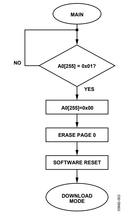
An I2C protocol can be implemented as part of user code to erase Page 0. Choose one dedicated address or a dedicated location in a table to be used as a flag for entering download mode. Based on the SFP reference design code, the companion code uses Address 0xFF (255) in the 0xA0 table.
When the host sends the command A0 W 0xFF 0x01 S, Page 0 is erased and a software reset is performed. Once Address 0x80014 is erased, and because P0.0 is permanently grounded, the part is placed automatically in download mode. This is demonstrated in the C code NoProt.c section of the companion code.
Using the Example Code
- Download NoProt.hex using I2CWSD.
- Click Run
Updating the User Code
- Send the command A0 W 0xFF 0x01 S via I2C. The part enters download mode automatically, as shown in Figure 2.
- Using the I2CWSD, download the updated code.
Note that this method doesn’t prevent accidental erasure of Page 0.
See the Adding Protection to the Protocol section for another solution using Flash protection.

Adding Protection to the Protocol
To have a more robust protocol, Page 0 can be protected. Flash/EE memory protection can be added easily. To take effect the part needs to be power cycled. This is shown in the companion code, in the C code Prot.c.
The following address locations are used in this example:
A0[251] MSB of FEEADR
A0[252] LSB of FEEADR
A0[253] MSB of FEEDAT
A0[254] LSB of FEEDAT
A0[255] status flag
State of the flag:
A0[255] = 0 by default
A0[255] = 1 means erase Page 0
A0[255] = 2 means protect Page 0
A0[255] = 3 means unprotect Page 0
Using the Example Code
- Download Prot.hex using I2CWSD.
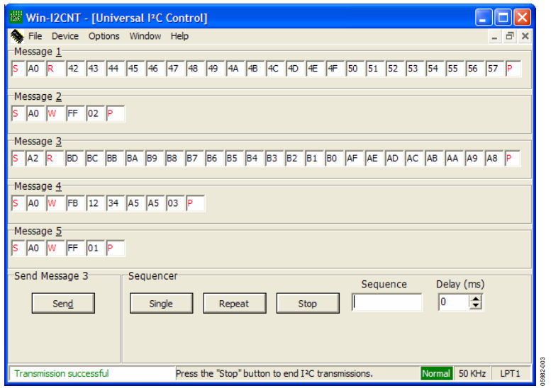
- To protect Page 0, send the command S A0 W FF 02 P via I2C (see Message 2 in Figure 3).
- Power cycle the part for the protection to take effect.
Updating the User Code
- To unprotect the page, send the command S A0 W FB 12 34 A5 A5 03 P via I2C (see Message 4 in Figure 3).
- Power cycle the part
- To erase Page 0, send the command S A0 W FF 01 P via I2C (see Message 5 in Figure 3).
- Use I2CWSD to download the updated code
To check how robust the code is, send the page erase command without unprotecting Page 0. User code still runs normally.

作者
