The TMP03 is a complete temperature data-acquisition system on a monolithic silicon chip. Including a silicon-based sensor, internal voltage reference, and sigma-delta A/D converter, it fits in a 3-pin (power, common, and output) TO-92 transistor package. Its digital output is a low-frequency variable-duty-cycle serial data stream, available at an open collector with 5-mA sink-current available. A companion product, the TMP04, is identical but has a CMOS/TTL-compatible output. The quiescent power requirement is a modest 1.3 mA at +5 V (4.5 to 7-V range).
Integrating the whole temperature-to-digital chain on a single chip saves space, design time, and money. In addition, the digital output and small number of leads enhances reliability and greatly simplifies isolation and remote operation. With fewer error sources, computation of the error budget is easier. The TMP03's digital output allows multi-channel systems to be constructed easily (additional sensors share a single-channel low-cost digitally-multiplexed decoder). Our TMP03 Evaluation Board is an example of low-cost multi-channel temperature-acquisition.
Typical applications of the TMP03 exist "everywhere"; a few examples include isolated sensors, environmental control systems, computer thermal monitoring, thermal protection, industrial process control, and power-system monitors.
Device Description: Analog Devices bandgap references generate both a constant voltage and a PTAT (proportional to absolute temperature) voltage. In the TMP03, these are applied as inputs to a first-order sigma-delta modulator. The device output is a 35-Hz (nominal) accurately mark-space-modulated digital signal that is insensitive to frequency. The TTL/CMOS compatible output allows the TMP03 to interface directly to standard logic.
Thus the TMP03 and TMP04 are well suited to interface directly to a microcontroller timer/counter input port and programmable logic arrays. The TMP04 provides a high-output-current logic output capable of driving a load capacitance of 1000 pF with minimal loss of switching-edge definition.
System Specifications: Since it is completely self-contained, the TMP03/TMP04 has specifications that are close to the final system specifications. A single temperature accuracy specification for the TMP03/04 combines errors due to the sensor's transfer function, signal conditioning and conversion. Typical accuracy (-25 to +100°C) is to within 1.5% (4% max), with nonlinearity of 0.5°C and power supply sensitivity of 0.7°C/V (1.2°C/V max). The device's operating temperature range is -55°C to +150°C.
Remote Operation: Outputs of traditional low-level voltage-output temperature transducers, when located remotely, will inevitably suffer signal degradation and errors due to noise pickup and/or ohmic losses. Some sensor schemes rely on analog output conditioning to produce a current output for long distance transmission (e.g., conventional 4-20 mA current loop). The current output eliminates ohmic signal losses, but the additional stage adds another term to the error budget calculation.
The digital output format of the TMP03/04 design allows this temperature transducer to be located away from the host computer system without degrading system accuracy; and the 35-Hz low-frequency output further insures data integrity over long distances. Cable capacitance between the TMP03 and its host computer will of course round the rising and falling edges of the square-wave output, but delays of the order of microseconds add negligible error relative to a 29-ms clock period. In most applications, temperature is a slowly changing variable, and a 35-Hz carrier has little effect on the measurement dynamic accuracy.
If a 100 × higher output frequency, say 3 kHz, had been chosen, the output circuitry would need to drive high currents into the load capacitance to keep the logic transitions acceptably short; a 1-ms asymmetry between the rise and fall times would have added about 1°C error. High output current requirements also increase the required supply current. An alternative solution for high-frequency, low-level transducer output: i.e., adding a local RS-232 (or RS-485) interface to drive a long cable, again increases the remotely supplied current required.
The table compares the sources of errors in a TMP03 based temperature measurement system to those in a system based on conventional analog temperature transducers:
| Thermocouple, Thermistor, RTD, etc | TMP03 | |
|
Sensor Error:
Nonlinearity, hysteresis, long-term drift
|
X |
X |
|
Signal Conditioning:
Nonlinearity, cold junction compensation drift, hysteresis, gain drift, offset (over temp range) |
X |
NA |
|
Digitization:
Nonlinearity, hysteresis, drift, missing codes, offset, charge transfer, reference drift
|
X |
X |
| Reference: Drift with temp; drift over time |
X |
NA |
| Signal degradation over distance | X |
NA |
| Multiplexer errors (multi channel systems) | X |
NA |
Only two terms are necessary for error budget calculation in the TMP03-the data sheet temperature measurement error spec and the quantization error for the external digital decode circuitry. A spreadsheet calculation can be used to select the desired counter resolution for the external digital decode circuitry. A 12-bit digital counter decode scheme introduces only 0.5°F quantization error.
TMP03 Output Decoding: The TMP03 sensor uses mark-space ratio modulation (Figure 2), embodying the relationships
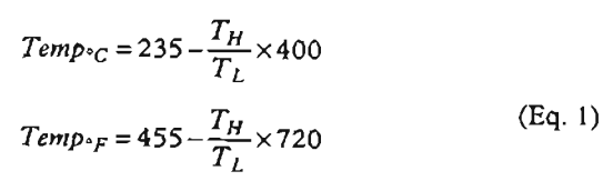
where TH andTL are the high and low periods of the square-wave output.
With the basic TMP03 sensor error specs, errors introduced in measuring TH andTL are the only other parameters needed to determine system accuracy. For example, if TH andTL are measured using a 125-kHz clock frequency and 12-bit counters, gated by the edges of the square-wave output, the quantization error is less than 0.5°F. TH andTL may be conveniently measured using discrete counters, programmable logic arrays, or from a microprocessor with an on-board timer/counter port. If absolute temperature is required, it can be calculated using a microprocessor or PC. The table indicates typical counter resolutions used in establishing TH andTL values, and the associated bit-error values at the various clock rates. The method of calculation is described in the TMP03/TMP04 data sheet.
Table 1. Counter Size and Clock Frequency Effects on Quantization Error
| Maximum Count Availiable | Maximum Temp Reqd. | Maximum Frequency | Quantization Error(25°C) | Quantization Error(77°F) |
| 4096 | 125°C | 94 kHz |
0.284°C |
0.512°F |
| 8192 | 125°C |
188 kHz |
0.142°C |
0.256°F |
| 16384 | 125°C |
376 kHz |
0.071°C |
0.128°F |
A frequency of 125 kHz is used in the evaluation board; it allows temperature measurement to 85°C (plus ~10°C over-range) and provides approximately 0.3°C resolution.
TMP03 Design Example–the Evaluation Board: A temperature measurement system was constructed using a programmable logic device for input multiplexing (of theTMP03 signals) and to derive TH andTL, a 5-V RS-232 converter, and a connector for up to eight TMP03s (Figure 3). This 8-channel temperature measurement system connects to the serial port of a IBM-compatible personal computer and allows temperature data to be gathered and recorded from remotely mounted TMP03 sensors. The PC selects the temperature sensor, logs data and performs the temperature calculation.
The PC first transmits the channel select byte. The digitally encoded temperature information from the TMP03 (the TH/TL square wave) is decoded using the programmable logic device, and the TH andTL count values are sent serially to the PC. The computer calculates the temperature using Eq. 1. A Windows based software package provides a graphical interface to display the data, and allows the user to save data to disk. Figure 4 shows a functional block diagram of the decoder architecture.
These functional blocks were implemented in the programmable logic device (an ICT, Inc. PA7140 PEEL Array): sensor address registers for channel selection; two 12-bit timers TH andTL quantization); serial data detection and synchronization, for transmission to the PC; output serial TH andTL count data; open/short sensor detector.
A microcontroller could have been used, but the ICT PEEL Array offered distinct advantages as the system control device:
- Ease of development, prototype, simulation, and debugging, and lower cost of development and production.
- Precise control of timing in a deterministic, register-rich, parallel hardware architecture
- Eight sensors could be accommodated without external digital multiplexer. More channels are added by using the required number of digital multiplexers or programmable logic devices. For example, a 144-channel system would use 10 external PLDs.
The TMP03 provides the capability for an "easy-to-design" temperature acquisition system. With the low cost and ease of expansion of its multiplexed Evaluation Board, applications from remote industrial temperature sensing to home temperature sensing are now cost-effective because of the low cost-per-channel and ease of integration. Time to market is short because of the ease of design and specification.
